Lexus NX: Installation
INSTALLATION
CAUTION / NOTICE / HINT
HINT:
A bolt without a torque specification is shown in the standard bolt chart.
Click here .gif)
PROCEDURE
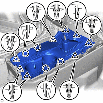
1. INSTALL CONSOLE BOX ASSEMBLY
(a) Attach the 4 guides to install the console box assembly.
(b) Install the 6 bolts.
(c) Connect the connectors and attach the clamps.
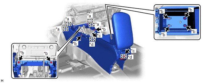
| *a | Guide | *b | Bolt |
| *c | Connector | *d | Clamp |
2. INSTALL CONSOLE BOX CARPET
(a) Install the console box carpet.
3. INSTALL CONSOLE BOX POCKET (w/o Wireless Charger)
(a) Install the console box pocket.
4. INSTALL REAR CONSOLE END PANEL SUB-ASSEMBLY
| (a) Connect the connectors. |
|
(b) Attach the 8 clips and 3 claws to install the rear console end panel sub-assembly.
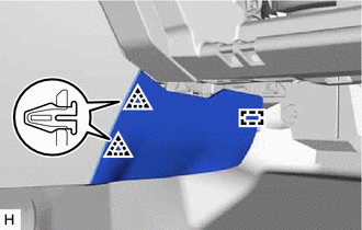
5. INSTALL INNER NO. 1 INSTRUMENT PANEL BRACE COVER LH
| (a) Attach the guide and 2 clips to install the inner No. 1 instrument panel brace cover LH. |
|
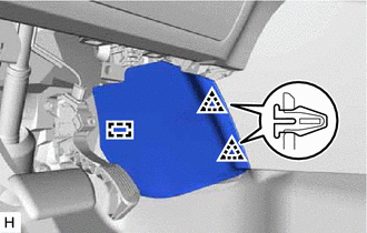
6. INSTALL INNER NO. 1 INSTRUMENT PANEL BRACE COVER RH
| (a) Attach the guide and 2 clips to install the inner No. 1 instrument panel brace cover RH. |
|
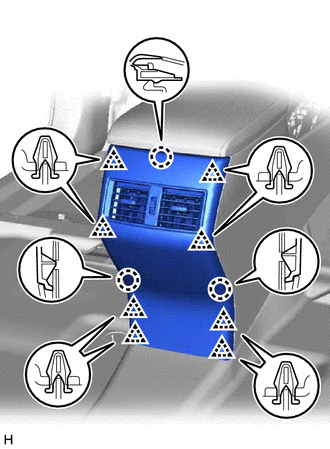
7. INSTALL UPPER REAR CONSOLE PANEL SUB-ASSEMBLY
| (a) Connect the connectors and attach the clamp. |
|
(b) Attach the 8 clips and 4 claws to install the upper rear console panel sub-assembly.
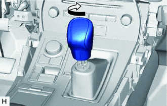
8. INSTALL SHIFT LEVER KNOB SUB-ASSEMBLY
| (a) Install the shift lever knob sub-assembly and twist it in the direction indicated by the arrow. |
|
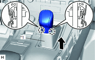
| (b) Attach the 2 claws to install the shifting hole cover sub-assembly. |
|
9. INSTALL CENTER INSTRUMENT CLUSTER FINISH PANEL ASSEMBLY
Click here
10. INSTALL MULTI-DISPLAY ASSEMBLY WITH BRACKET
Click here
11. INSTALL INSTRUMENT PANEL FINISH PLATE
Click here
12. INSTALL NO. 2 INSTRUMENT PANEL SAFETY PAD SUB-ASSEMBLY
Click here
13. INSTALL INSTRUMENT SIDE PANEL RH
Click here
14. INSTALL NO. 1 SWITCH HOLE BASE
Click here
15. INSTALL LOWER NO. 1 INSTRUMENT PANEL FINISH PANEL
Click here
16. INSTALL NO. 1 INSTRUMENT PANEL UNDER COVER SUB-ASSEMBLY
Click here
17. INSTALL NO. 1 INSTRUMENT PANEL SAFETY PAD SUB-ASSEMBLY
Click here
18. INSTALL INSTRUMENT SIDE PANEL LH
Click here
19. INSTALL UPPER NO. 2 CONSOLE PANEL GARNISH
Click here
20. INSTALL UPPER NO. 1 CONSOLE PANEL GARNISH
Click here
21. INSTALL UPPER REAR CONSOLE PANEL
Click here
22. INSTALL CONSOLE ARMREST ASSEMBLY
Click here
READ NEXT:
 Components
COMPONENTS ILLUSTRATION *1 COWL SIDE TRIM BOARD LH *2 DOOR SCUFF PLATE ASSEMBLY LH *3 FRONT FLOOR CARPET ASSEMBLY *4 NO. 4 DASH PANEL INSULATOR PAD (FRONT FLOOR FOOTREST)
Removal
REMOVAL PROCEDURE 1. REMOVE CONSOLE BOX ASSEMBLY Click here 2. REMOVE DOOR SCUFF PLATE ASSEMBLY LH Click here 3. REMOVE COWL SIDE TRIM BOARD LH Click here 4. DISCONNECT FRONT FLOOR CARPET
SEE MORE:
Replacement
REPLACEMENT CAUTION / NOTICE / HINT NOTICE:
When the brake pedal is first depressed after replacing the brake pads or pushing back the disc brake piston, DTC C1214 may be output. As there is no malfunction, clear the DTC.
While the auxiliary battery is connected, even if the power switch is off
Removal
REMOVAL CAUTION / NOTICE / HINT CAUTION: Wear protective gloves. Sharp areas on the parts may injure your hands. PROCEDURE 1. REMOVE REAR SEATBACK ASSEMBLY LH (a) for Manual Seat: Click here (b) for Power Seat: Click here 2. REMOVE REAR SEATBACK ASSEMBLY RH (a) for Manual Seat: Click here (b)
