Lexus NX: Disassembly
DISASSEMBLY
PROCEDURE
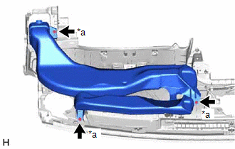
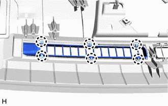
1. REMOVE NO. 1 HEATER TO REGISTER DUCT SUB-ASSEMBLY
| (a) Remove the 3 screws <A> or <B> and No. 1 heater to register duct sub-assembly. |
|
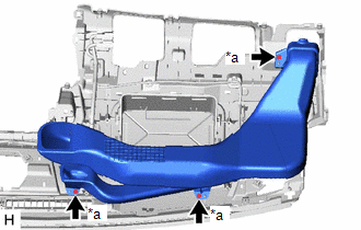
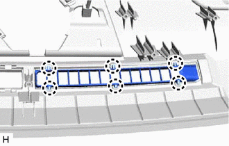
2. REMOVE NO. 2 HEATER TO REGISTER DUCT SUB-ASSEMBLY
| (a) Remove the 3 screws <A> or <B> and No. 2 heater to register duct sub-assembly. |
|
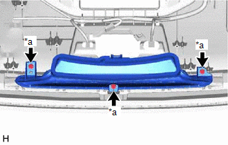
3. REMOVE DEFROSTER NOZZLE ASSEMBLY
| (a) Remove the 3 screws <A> or <B> and defroster nozzle assembly. |
|
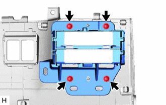
4. REMOVE METER HOOD SET BRACKET
| (a) Detach the clamp. |
|
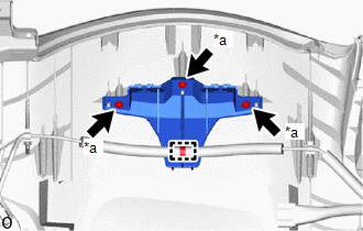
(b) Remove the 3 screws <A> or <B> and meter hood set bracket.
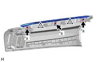
5. REMOVE NO. 2 DEFROSTER NOZZLE GARNISH
| (a) Detach the 6 claws and remove the No. 2 defroster nozzle garnish. |
|
6. REMOVE NO. 1 DEFROSTER NOZZLE GARNISH
| (a) Detach the 6 claws and remove the No. 1 defroster nozzle garnish. |
|
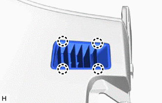
7. REMOVE SIDE DEFROSTER NOZZLE LH
| (a) Detach the 4 claws and remove the side defroster nozzle LH. |
|
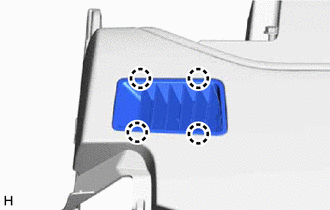
8. REMOVE SIDE DEFROSTER NOZZLE RH
| (a) Detach the 4 claws and remove the side defroster nozzle RH. |
|
9. REMOVE NO. 1 INSTRUMENT PANEL CUSHION
(a) Remove the No. 1 instrument panel cushion.
10. REMOVE NO. 2 INSTRUMENT PANEL CUSHION
(a) Remove the No. 2 instrument panel cushion.
11. REMOVE NO. 2 INSTRUMENT PANEL WIRE
Click here .gif)
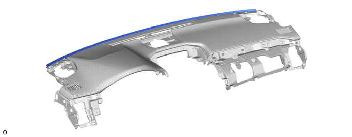
12. REMOVE INSTRUMENT PANEL PASSENGER WITHOUT DOOR AIRBAG ASSEMBLY
Click here
13. REMOVE NAVIGATION ANTENNA ASSEMBLY WITH BRACKET
Click here
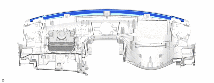
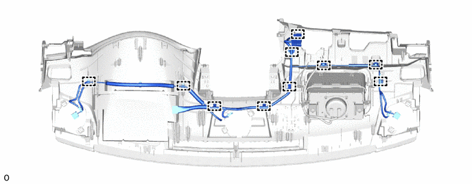
14. REMOVE INSTRUMENT PANEL WIRE
(a) Detach the clamps and remove the instrument panel wire.
15. REMOVE METER MIRROR SUB-ASSEMBLY (HEADUP DISPLAY) (w/ Headup Display)
Click here
16. REMOVE INSTRUMENT CLUSTER FINISH PANEL ASSEMBLY (w/ Headup Display)
| (a) Detach the 2 claws and 3 clips. |
|
(b) Detach the 3 guides and remove the instrument cluster finish panel assembly.
17. REMOVE NO. 2 INSTRUMENT CLUSTER FINISH PANEL GARNISH
| (a) Remove the 3 screws <A> or <B>. |
|
(b) Detach the 2 clips and remove the No. 2 instrument cluster finish panel garnish.
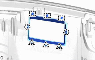
18. REMOVE LOWER NO. 2 INSTRUMENT PANEL FINISH PANEL
| (a) Remove the 4 screws and lower No. 2 instrument panel finish panel. |
|
READ NEXT:
 Reassembly
REASSEMBLY PROCEDURE 1. INSTALL LOWER NO. 2 INSTRUMENT PANEL FINISH PANEL (a) Install the lower No. 2 instrument panel finish panel with the 4 screws. 2. INSTALL NO. 2 INSTRUMENT CLUSTE
Installation
INSTALLATION CAUTION / NOTICE / HINT HINT: A bolt without a torque specification is shown in the standard bolt chart. Click here PROCEDURE 1. INSTALL UPPER INSTRUMENT PANEL SUB-ASSEMBLY (a) Attach t
SEE MORE:
Interior Light Auto Cut Circuit
DESCRIPTION The main body ECU (multiplex network body ECU) controls the DOME CUT relay. WIRING DIAGRAM CAUTION / NOTICE / HINT NOTICE:
Inspect the fuses for circuits related to this system before performing the following procedure.
Recognition code registration is necessary when replacing the
Removal
REMOVAL CAUTION / NOTICE / HINT HINT:
Use the same procedure for the RH and LH sides.
The procedure listed below is for the LH side.
PROCEDURE 1. REMOVE NO. 3 DECK BOARD SUB-ASSEMBLY Click here 2. REMOVE REAR DECK FLOOR BOX Click here 3. REMOVE DECK FLOOR BOX LH Click here 4. PRECAUTIO
