Lexus NX: Disassembly
Lexus NX Service Manual / Drivetrain / P314 (hybrid Transmission / Transaxle) / Shift Lever / Disassembly
DISASSEMBLY
PROCEDURE
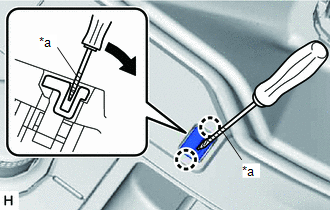
1. REMOVE SHIFT LEVER CAP
| (a) Using a screwdriver with its tip wrapped with protective tape, detach the 2 claws and remove the shift lever cap from the shift position indicator. |
|
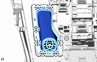
2. REMOVE SHIFTING HOLE COVER SUB-ASSEMBLY
| (a) Detach the 7 claws and remove the shifting hole cover sub-assembly from the rear upper console panel sub-assembly. |
|
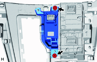
3. REMOVE SHIFT POSITION INDICATOR
| (a) Remove the 2 screws and shift position indicator from the rear upper console panel sub-assembly. |
|
READ NEXT:
 Inspection
INSPECTION PROCEDURE 1. INSPECT SHIFT LOCK CONTROL ECU (a) Measure the voltage according to the value(s) in the table below. Standard Voltage: Tester Connection Condition Specified Conditio
Reassembly
REASSEMBLY PROCEDURE 1. INSTALL SHIFT POSITION INDICATOR (a) Install the shift position indicator to the rear upper console panel sub-assembly with the 2 screws. 2. INSTALL SHIFTING HOL
Installation
INSTALLATION PROCEDURE 1. INSTALL SHIFT LEVER ASSEMBLY (a) Temporarily install the shift lever assembly with the 4 bolts. (b) Tighten the bolts in the order shown in the illustration. Torque: 12 N
SEE MORE:
On-vehicle Inspection
ON-VEHICLE INSPECTION PROCEDURE 1. INSPECT RESERVOIR CAP (a) Measure the valve opening pressure. *a O-Ring *b Rubber Packing (1) If there are water stains or foreign matter on the O-ring, clean it with water and finger scouring. (2) Check that the O-ring is not deformed, cracked or sw
ECO Switch Circuit
DESCRIPTION When the integration control and panel assembly (ECO mode switch) is turned on, the air conditioning amplifier assembly receives an integration control and panel assembly (ECO mode switch) ON signal and controls the air conditioning to enhance fuel efficiency. WIRING DIAGRAM CAUTION / N
© 2016-2024 Copyright www.lexunx.com
