Lexus NX: Inspection
INSPECTION
PROCEDURE
1. INSPECT BACK DOOR LOCK ASSEMBLY (w/o Power Back Door)
| (a) Check the operation of the door lock motor. (1) Move the back door lock assembly to the lock position. (2) Apply auxiliary battery voltage to the door lock motor assembly and check the operation of the door lock motor. OK:
If the result is not as specified, replace the back door lock assembly. |
|
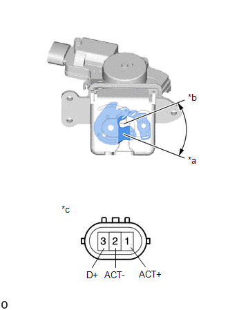
(b) Check the operation of the door courtesy switch.
(1) Measure the resistance according to the value(s) in the table below.
Standard Resistance:
| Tester Connection | Condition | Specified Condition |
|---|---|---|
| 3 (D+) - 2 (ACT-) | Lock | 10 kΩ or higher |
| 3 (D+) - 2 (ACT-) | Unlock | Below 1 Ω |
If the result is not as specified, replace the back door lock assembly.
2. INSPECT BACK DOOR LOCK ASSEMBLY (w/ Power Back Door)
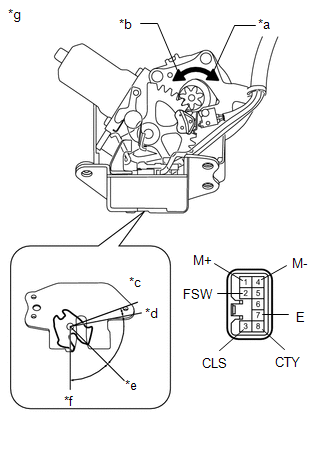
| *a | Clockwise |
| *b | Counterclockwise |
| *c | Over-latch |
| *d | Full-latch |
| *e | Half-latch |
| *f | Open-latch |
| *g | Component without harness connected (Back Door Lock Assembly) |
(a) Apply auxiliary battery voltage to the door lock motor and check the operation of the door lock motor.
OK:| Measurement Condition | Specified Condition |
|---|---|
| Auxiliary battery positive (+) → 1 (M+) Auxiliary battery negative (-) → 4 (M-) | Latch turns to full-latch position (clockwise rotation) |
| Auxiliary battery positive (+) → 4 (M-) Auxiliary battery negative (-) → 1 (M+) | Latch turns to open-latch position (counterclockwise rotation) |
If the result is not as specified, replace the back door lock assembly.
(b) Check the operation of the latch switch.
(1) Measure the resistance according to the value(s) in the table below.
Standard Resistance| Tester Connection | Condition | Specified Condition |
|---|---|---|
| 3 (CLS) - 7 (E) | Open-latch | Below 1 Ω |
| 3 (CLS) - 7 (E) | Open-latch → Half-latch | Below 1 Ω → 10 kΩ or higher |
| 3 (CLS) - 7 (E) | Half-latch | 10 kΩ or higher |
| 3 (CLS) - 7 (E) | Full-latch | 10 kΩ or higher |
| 3 (CLS) - 7 (E) | Over-latch | 10 kΩ or higher → Below 1 Ω → 10 kΩ or higher |
| Tester Connection | Condition | Specified Condition |
|---|---|---|
| 3 (CLS) - 7 (E) | Full-latch | 10 kΩ or higher |
| 3 (CLS) - 7 (E) | Half-latch | 10 kΩ or higher |
| 3 (CLS) - 7 (E) | Half-latch → Open-latch | 10 kΩ or higher → Below 1 Ω |
| 3 (CLS) - 7 (E) | Open-latch | Below 1 Ω |
If the result is not as specified, replace the back door lock assembly.
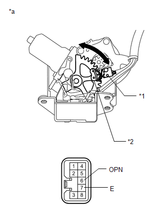
(c) Check the operation of the pawl switch.
(1) Measure the resistance according to the value(s) in the table below.
Standard Resistance| Tester Connection | Condition | Specified Condition |
|---|---|---|
| 2 (FSW) - 7 (E) | Open-latch | 10 kΩ or higher |
| 2 (FSW) - 7 (E) | Open-latch → Half-latch | 10 kΩ or higher → Below 1 Ω → 10 kΩ or higher |
| 2 (FSW) - 7 (E) | Half-latch | 10 kΩ or higher |
| 2 (FSW) - 7 (E) | Half-latch → Full-latch | 10 kΩ or higher → Below 1 Ω → 10 kΩ or higher |
| 2 (FSW) - 7 (E) | Full-latch | 10 kΩ or higher |
If the result is not as specified, replace the back door lock assembly.
(d) Check the operation of the back door courtesy switch.
(1) Measure the resistance according to the value(s) in the table below.
Standard Resistance| Tester Connection | Condition | Specified Condition |
|---|---|---|
| 8 (CTY) - 7 (E) | Open-latch | Below 1 Ω |
| 8 (CTY) - 7 (E) | Half-latch | Below 1 Ω |
| 8 (CTY) - 7 (E) | Half-latch → Full-latch | Below 1 Ω → 10 kΩ or higher |
| 8 (CTY) - 7 (E) | Full-latch | 10 kΩ or higher |
| 8 (CTY) - 7 (E) | Over-latch | 10 kΩ or higher |
If the result is not as specified, replace the back door lock assembly.
| (e) Check the operation of the selector switch. (1) Measure the resistance according to the value(s) in the table below. Standard Resistance
If the result is not as specified, replace the back door lock assembly. |
|
READ NEXT:
 Installation
INSTALLATION PROCEDURE 1. INSTALL BACK DOOR LOCK ASSEMBLY (w/ Power Back Door) NOTICE:
When installing a new back door lock assembly, if there is any tape stuck to it, remove the tape.
When insta
Components
COMPONENTS ILLUSTRATION *1 DECK FLOOR BOX LH *2 NO. 3 DECK BOARD SUB-ASSEMBLY *3 REAR DECK FLOOR BOX *4 NEGATIVE AUXILIARY BATTERY TERMINAL N*m (kgf*cm, ft.*lbf): Specified
SEE MORE:
Installation
INSTALLATION PROCEDURE 1. INSTALL ULTRASONIC SENSOR CUSHION SET HINT: Perform the following procedure only when replacement of a ultrasonic sensor cushion set is necessary. (a) Install the ultrasonic sensor cushion set as shown in the illustration. Install in this Direction - - 2. INST
Data List / Active Test
DATA LIST / ACTIVE TEST DATA LIST NOTICE: In the table below, the values listed under "Normal Condition" are reference values. Do not depend solely on these reference values when deciding whether a part is faulty or not. HINT: Using the Techstream to read the Data List allows the values or states of
