Lexus NX: Emergency Call Switch Illumination Circuit
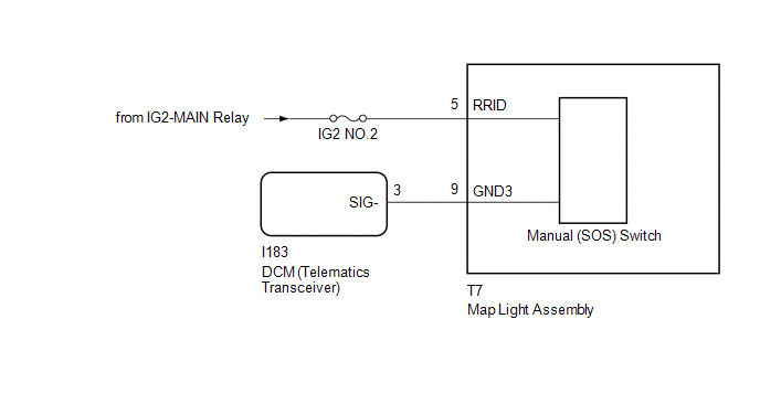
WIRING DIAGRAM
CAUTION / NOTICE / HINT
NOTICE:
-
Depending on the parts that are replaced during vehicle inspection or maintenance, performing initialization, registration or calibration may be needed. Refer to Precaution for safety connect system.
Click here
.gif)
- Inspect the fuses for circuits related to this system before performing the following procedure.
PROCEDURE
| 1. | CHECK HARNESS AND CONNECTOR (MAP LIGHT ASSEMBLY POWER SOURCE) |
(a) Disconnect the I183 DCM (telematics transceiver) connector.
(b) Disconnect the T7 map light assembly connector.
(c) Measure the voltage according to the value(s) in the table below.
Standard Voltage:
| Tester Connection | Switch Condition | Specified Condition |
|---|---|---|
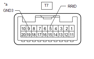
| T7-5 (RRID) - Body Ground | Power switch on (IG) | 11 to 14 V |
(d) Measure the resistance according to the value(s) in the table below.
Standard Resistance:
| Tester Connection | Condition | Specified Condition |
|---|---|---|
| I183-3 (SIG-) - T7-9 (GND3) | Always | Below 1 Ω |
| I183-3 (SIG-) or T7-9 (GND3) - Body ground | Always | 10 kΩ or higher |
| NG | .gif) | REPAIR OR REPLACE HARNESS OR CONNECTOR |
|
.gif)
| 2. | INSPECT MAP LIGHT ASSEMBLY (MANUAL [SOS] SWITCH) |
| (a) Remove the map light assembly. Click here |
|
(b) Apply battery voltage to the connector and check that the manual (SOS) switch illumination comes on.
OK:
| Measurement Condition | Condition | Specified Condition |
|---|---|---|
| Battery positive (+) → T7-5 (RRID) Battery negative (-) → T7-9 (GND3) | Always | Manual (SOS) switch illumination comes on |
| NG | | REPLACE MAP LIGHT ASSEMBLY (MANUAL [SOS] SWITCH) |
|
| 3. | REPLACE DCM (TELEMATICS TRANSCEIVER) |
(a) Replace the DCM (telematics transceiver).
Click here
NOTICE:
- The power switch must be off.
- Do not exchange the DCM (telematics transceiver) with one from another vehicle.
| NEXT | | PERFORM DCM ACTIVATION |
READ NEXT:
 Telephone And Gps Antenna
ComponentsCOMPONENTS ILLUSTRATION *1 DECK FLOOR BOX LH *2 NO. 3 DECK BOARD SUB-ASSEMBLY *3 REAR DECK FLOOR BOX *4 NEGATIVE AUXILIARY BATTERY TERMINAL N*m (kgf*cm, ft.*lbf):
SEE MORE:
Terminals Of Ecu
TERMINALS OF ECU CHECK MAIN BODY ECU (MULTIPLEX NETWORK BODY ECU), INSTRUMENT PANEL JUNCTION BLOCK ASSEMBLY *1 Main Body ECU (Multiplex Network Body ECU) - - (a) Remove the main body ECU (multiplex network body ECU) from the instrument panel junction block assembly. Click here (b) Me
Removal
REMOVAL PROCEDURE 1. PRECAUTION NOTICE:
Be sure to read Precaution thoroughly before servicing.
Click here
Handle components indoors as much as possible to prevent foreign matter from entering and adhering to headlight assembly components.
Do not reuse parts which have reduced fastening abi
