Lexus NX: Removal
REMOVAL
PROCEDURE
1. PRECAUTION
NOTICE:
-
Be sure to read Precaution thoroughly before servicing.
Click here
.gif)
- Handle components indoors as much as possible to prevent foreign matter from entering and adhering to headlight assembly components.
- Do not reuse parts which have reduced fastening ability due to thread damage.
- When installing components, make sure that the wire harness is not pinched or pulled.
- Do not use solvent to clean components. Only clean them with a dry cloth.
HINT:
- Use the same procedure for the RH and LH sides.
- The procedure listed below is for the LH side.
2. REMOVE HEADLIGHT ASSEMBLY LH
for Single Beam Headlight:
Click here
for Triple Beam Headlight:
Click here
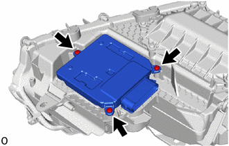
3. REMOVE HEADLIGHT ECU SUB-ASSEMBLY LH
NOTICE:
- If the headlight ECU sub-assembly LH has been dropped, replace it with a new one.
- If the headlight ECU sub-assembly LH has been removed, replace the headlight gasket with a new one.
- When removing the headlight ECU sub-assembly LH, use static electricity countermeasures SST (desktop anti-static mat set) and observe all precautions to prevent damage to the system by electrostatic discharge (ESD).
SST: 09890-47010
09891-04010
09891-04020
09891-04030
09891-04040
| (a) Remove the 3 screws and headlight ECU sub-assembly LH. |
|
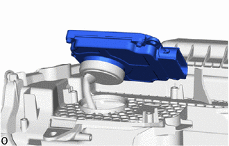
| (b) Disconnect the connector cover. |
|
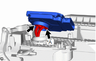
| (c) Disconnect each connector. |
|
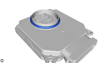
4. REMOVE HEADLIGHT GASKET
NOTICE:
- If the headlight gasket has been removed, replace it with a new one.
- When removing the headlight gasket, use static electricity countermeasures SST (desktop anti-static mat set) and observe all precautions to prevent damage to the system by electrostatic discharge (ESD).
SST: 09890-47010
09891-04010
09891-04020
09891-04030
09891-04040
| (a) Remove the headlight gasket. |
|
READ NEXT:
 Installation
INSTALLATION CAUTION / NOTICE / HINT NOTICE:
Handle components indoors as much as possible to prevent foreign matter from entering and adhering to headlight assembly components.
Do not reuse part
Height Control Sensor
ComponentsCOMPONENTS ILLUSTRATION *1 REAR HEIGHT CONTROL SENSOR SUB-ASSEMBLY - - RemovalREMOVAL PROCEDURE 1. REMOVE REAR HEIGHT CONTROL SENSOR SUB-ASSEMBLY (a) Disconnect the connect
High Mounted Stop Light Assembly
ComponentsCOMPONENTS ILLUSTRATION *1 CENTER STOP LIGHT ASSEMBLY *2 REAR SPOILER ASSEMBLY RemovalREMOVAL PROCEDURE 1. REMOVE REAR SPOILER ASSEMBLY Click here 2. REMOVE CENTER STOP LIGH
SEE MORE:
Blind Spot Monitor Master Module Beam Axis Inspection Incomplete (C1ABB)
DESCRIPTION This DTC is stored when a beam axis inspection has not been performed for the blind spot monitor sensor LH. HINT: This DTC is always stored after replacing a blind spot monitor sensor. The purpose of this DTC is to ensure that beam axis inspection is performed. Completing the beam axis i
Footwell Light Circuit
DESCRIPTION The main body ECU (multiplex network body ECU) controls the operation of the following lights:
No. 1 interior illumination light assembly LH
No. 1 interior illumination light assembly RH
WIRING DIAGRAM CAUTION / NOTICE / HINT NOTICE:
Inspect the fuses for circuits related to
© 2016-2024 Copyright www.lexunx.com
