Lexus NX: Footwell Light
Components
COMPONENTS
ILLUSTRATION
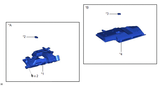
| *A | for Driver Side | *B | for Front Passenger Side |
| *1 | NO. 1 INSTRUMENT PANEL UNDER COVER SUB-ASSEMBLY | *2 | NO. 1 INTERIOR ILLUMINATION LIGHT ASSEMBLY LH |
| *3 | NO. 1 INTERIOR ILLUMINATION LIGHT ASSEMBLY RH | *4 | NO. 2 INSTRUMENT PANEL UNDER COVER SUB-ASSEMBLY |
Removal
REMOVAL
PROCEDURE
1. DISCONNECT NO. 1 INSTRUMENT PANEL UNDER COVER SUB-ASSEMBLY (for Driver Side)
| (a) Remove the 2 screws. |
|
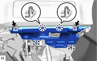
(b) Detach the 2 claws and 2 guides and disconnect the No. 1 instrument panel under cover sub-assembly.
2. REMOVE NO. 1 INTERIOR ILLUMINATION LIGHT ASSEMBLY LH (for Driver Side)
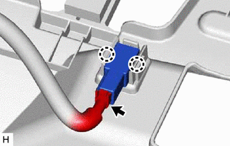
| (a) Disconnect the connector. |
|
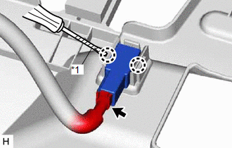
(b) Using a screwdriver, detach the 2 claws and remove the No. 1 interior illumination light assembly LH.
HINT:
Tape the screwdriver tip before use.
3. DISCONNECT NO. 2 INSTRUMENT PANEL UNDER COVER SUB-ASSEMBLY (for Front Passenger Side)
| (a) Using moulding remover A, detach the 3 claws and guide and disconnect the No. 2 instrument panel under cover sub-assembly. |
|
.png)
4. REMOVE NO. 1 INTERIOR ILLUMINATION LIGHT ASSEMBLY RH (for Front Passenger Side)
| (a) Disconnect the connector. |
|
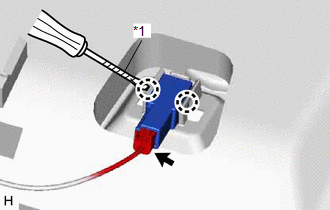
(b) Using a screwdriver, detach the 2 claws and remove the No. 1 interior illumination light assembly RH.
HINT:
Tape the screwdriver tip before use.
Inspection
INSPECTION
PROCEDURE
1. INSPECT NO. 1 INTERIOR ILLUMINATION LIGHT ASSEMBLY LH (for Driver Side)
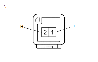
| (a) Apply battery voltage to the connector and check the light illumination condition. OK:
If the result is not as specified, replace the No. 1 interior illumination light assembly LH. |
|
2. INSPECT NO. 1 INTERIOR ILLUMINATION LIGHT ASSEMBLY RH (for Front Passenger Side)
| (a) Apply battery voltage to the connector and check the light illumination condition. OK:
If the result is not as specified, replace the No. 1 interior illumination light assembly RH. |
|
Installation
INSTALLATION
PROCEDURE
1. INSTALL NO. 1 INTERIOR ILLUMINATION LIGHT ASSEMBLY LH (for Driver Side)
| (a) Attach the 2 claws to install the No. 1 interior illumination light assembly LH. |
|
(b) Connect the connector.
2. CONNECT NO. 1 INSTRUMENT PANEL UNDER COVER SUB-ASSEMBLY (for Driver Side)
| (a) Attach the 2 guides and 2 claws to connect the No. 1 instrument panel under cover sub-assembly. |
|
.png)
(b) Install the 2 screws.
3. INSTALL NO. 1 INTERIOR ILLUMINATION LIGHT ASSEMBLY RH (for Front Passenger Side)
| (a) Attach the 2 claws to install the No. 1 interior illumination light assembly RH. |
|
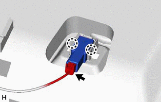
(b) Connect the connector.
4. CONNECT NO. 2 INSTRUMENT PANEL UNDER COVER SUB-ASSEMBLY (for Front Passenger Side)
| (a) Attach the guide and 3 claws to connect the No. 2 instrument panel under cover sub-assembly. |
|
.png)
READ NEXT:
 Front Door Courtesy Switch
ComponentsCOMPONENTS ILLUSTRATION *1 FRONT DOOR COURTESY LIGHT SWITCH ASSEMBLY - - N*m (kgf*cm, ft.*lbf): Specified torque - - RemovalREMOVAL CAUTION / NOTICE / HINT HINT:
Components
COMPONENTS ILLUSTRATION *1 DECK FLOOR BOX LH *2 NO. 3 DECK BOARD SUB-ASSEMBLY *3 REAR DECK FLOOR BOX *4 NEGATIVE AUXILIARY BATTERY TERMINAL N*m (kgf*cm, ft.*lbf): Specified
SEE MORE:
Inspection
INSPECTION PROCEDURE 1. CHECK BRAKE CYLINDER AND PISTON (a) Check the cylinder bore and piston for rust or scoring. If necessary, replace the disc brake cylinder and piston. 2. CHECK PAD LINING THICKNESS (a) Using a ruler, measure the pad lining thickness. Standard thickness: 10.0 mm (0.394 in.) Mi
Installation
INSTALLATION PROCEDURE 1. INSTALL AUTOMATIC LIGHT CONTROL SENSOR (a) Attach the 2 claws to install the automatic light control sensor. 2. INSTALL NO. 1 SPEAKER OPENING COVER ASSEMBLY Click here 3. INSPECT AUTOMATIC LIGHT CONTROL SYSTEM for Single Beam Headlight: Click here for Triple Beam He
