Lexus NX: Fuel Sender Gauge Assembly
Components
COMPONENTS
ILLUSTRATION
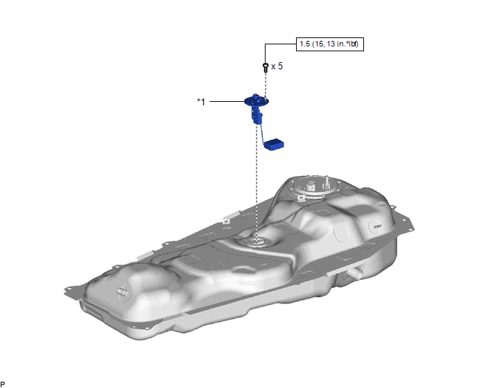
| *1 | FUEL SENDER GAUGE ASSEMBLY | - | - |
.png) | N*m (kgf*cm, ft.*lbf): Specified torque | - | - |
Removal
REMOVAL
PROCEDURE
1. REMOVE FUEL TANK ASSEMBLY
Click here .gif)
2. REMOVE FUEL SENDER GAUGE ASSEMBLY
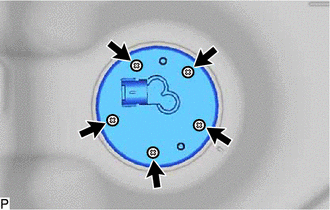
| (a) Remove the 5 screws and fuel sender gauge assembly from the fuel tank assembly. |
|
Inspection
INSPECTION
PROCEDURE
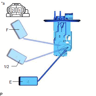
1. INSPECT FUEL SENDER GAUGE ASSEMBLY
(a) Check that the float moves smoothly between F and E.
| (b) Measure the resistance according to the value(s) in the table below. Standard Resistance:
If the value is not as specified, replace the fuel sender gauge assembly. |
|
Installation
INSTALLATION
PROCEDURE
1. INSTALL FUEL SENDER GAUGE ASSEMBLY
(a) Install the fuel sender gauge assembly to the fuel tank assembly with the 5 screws.
Torque:
1.5 N·m {15 kgf·cm, 13 in·lbf}
2. INSTALL FUEL TANK ASSEMBLY
Click here .gif)
READ NEXT:
 Parts Location
PARTS LOCATION ILLUSTRATION *1 FUEL INJECTOR ASSEMBLY *2 FUEL PUMP *3 FUEL SENDER GAUGE ASSEMBLY *4 EFI-MAIN RELAY *5 EFI-MAIN NO. 2 RELAY *6 ECM *7 FUEL PUMP CONTR
System Diagram
SYSTEM DIAGRAM
SEE MORE:
Inspection
INSPECTION PROCEDURE 1. INSPECT CHARCOAL CANISTER ASSEMBLY (a) Visually check the charcoal canister assembly for cracks or damage. If cracks or damage is found, replace the charcoal canister assembly. (b) Check the canister operation. *1 Connector *a Vent Line Port *b
Hybrid transmission
Select the shift position depending
on your purpose and situation.
Shift position purpose and functions
*1: To improve fuel efficiency and reduce
noise, shift the shift lever to D for normal
driving.
You can choose gear range suitable for
your driving situation by operating the
paddle shif
