Lexus NX: Generator Control Module (P0A1A-166)
DESCRIPTION
The MG ECU, which is built into the inverter with converter assembly, monitors its internal operation and will store DTCs if the system is malfunctioning. If any of the following DTCs are output, replace the inverter with converter assembly.
| DTC No. | Detection Item | DTC Detection Condition | Trouble Area | MIL | Warning Indicate |
|---|---|---|---|---|---|
| P0A1A-166 | Generator Control Module | MG ECU internal malfunction: R/D converter NM stop error (1 trip detection logic) | Inverter with converter assembly | Comes on | Master Warning Light: Comes on |
| DTC No. | Data List |
|---|---|
| P0A1A-166 | - |
MONITOR DESCRIPTION
The MG ECU performs many diagnostic tests to verify proper operation of internal ECU systems. In one of these tests, the MG ECU checks for an R/D (Resolver/Digital Converter) malfunction involving the generator resolver. If the MG ECU detects an R/D error, it will conclude that there is an internal malfunction involving the generator resolver and the hybrid vehicle control ECU will illuminate the MIL and store a DTC.
MONITOR STRATEGY
| Related DTCs | P0A1A (INF 166): RD converter NM signal stop abnormality |
| Required sensors/components | Inverter with converter assembly (MG ECU) |
| Frequency of operation | Continuous |
| Duration | TMC's intellectual property |
| MIL operation | 1 driving cycle |
| Sequence of operation | None |
TYPICAL ENABLING CONDITIONS
| The monitor will run whenever the following DTCs are not stored | TMC's intellectual property |
| Other conditions belong to TMC's intellectual property | - |
TYPICAL MALFUNCTION THRESHOLDS
| TMC's intellectual property | - |
COMPONENT OPERATING RANGE
| Hybrid vehicle control ECU | DTC P0A1A (INF 166) is not detected |
CONFIRMATION DRIVING PATTERN
- Connect the Techstream to the DLC3.
- Turn the power switch on (IG) and turn the Techstream on.
- Clear the DTCs (even if no DTCs are stored, perform the clear DTC procedure).
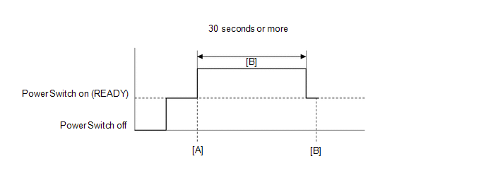
- Turn the power switch off and wait for 30 seconds or more.
- Turn the power switch on (READY).
- With the vehicle stopped with the shift lever in P, depress the accelerator pedal and start the engine. [A]
- Depress the accelerator pedal and keep the engine running for 30 seconds or more. [B]
- Enter the following menus: Powertrain / Hybrid Control / Trouble Codes. [C]
-
Read the current DTCs.
HINT:
- If a current DTC is output, the system is malfunctioning.
- If current DTCs are not output, check for permanent DTCs.
- Check that the permanent DTCs are cleared.
- If the permanent DTCs are not cleared, perform the universal trip, and then check for permanent DTCs again.
CAUTION / NOTICE / HINT
HINT:
If DTC P0A1A-166 is output, clear the DTCs, perform the following procedure, and check that the same DTC is not output after the repair.
- Turn the power switch on (READY).
- With the vehicle stopped and the shift lever in P, depress the accelerator pedal and start the engine.
- Depress the accelerator pedal and keep the engine running for 30 seconds or more.
PROCEDURE
| 1. | REPLACE INVERTER WITH CONVERTER ASSEMBLY |
Click here .gif)
| NEXT | .gif) | COMPLETED |
READ NEXT:
 Generator Control Module (P0A1A-517,P0A1A-809)
DTC SUMMARY MALFUNCTION DESCRIPTION These DTCs indicate that a large current flowed in the inverter for the generator. The cause of this malfunction may be one of the following: Internal inverter mal
Generator Control Module (P0A1A-658,P0A1A-791,P1C2A-155,P1CA6-156,P3133-659)
DESCRIPTION The MG ECU, which is built into the inverter with converter assembly, monitors its internal operation and will store DTCs if the system is malfunctioning. If any of the following DTCs are
Drive Motor "A" Control Module (P0A1B-198)
DESCRIPTION The MG ECU, which is built into the inverter with converter assembly, monitors its internal operation and will store DTCs if the system is malfunctioning. If any of the following DTCs are
SEE MORE:
Installation
INSTALLATION PROCEDURE 1. INSTALL NAVIGATION ANTENNA ASSEMBLY 2. INSTALL NAVIGATION ANTENNA BRACKET (a) Attach the 4 guides to install the navigation antenna assembly as shown in the illustration. (b) Attach the 2 claws to install the navigation antenna assembly. 3. INSTALL ANTENNA CO
Steering Angle Initialization Incomplete (C1694)
DESCRIPTION This DTC is stored when the rear television camera assembly judges that the maximum steering angle has not been memorized (steering angle setting is incomplete). DTC No. Detection Item DTC Detection Condition Trouble Area C1694 Steering Angle Initialization Incomplete Ma
