Lexus NX: Headlight Dimmer Switch Circuit
DESCRIPTION
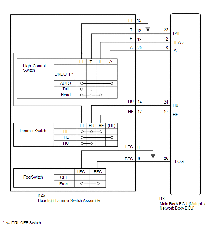
The main body ECU (multiplex network body ECU) receives light control switch signals, dimmer switch signals, fog light switch signals from the headlight dimmer switch.
WIRING DIAGRAM
CAUTION / NOTICE / HINT
NOTICE:
- Recognition code registration is necessary when replacing the main body ECU (multiplex network body ECU).
- If the main body ECU (multiplex network body ECU) is replaced, refer to Registration.
PROCEDURE
| 1. | READ VALUE USING TECHSTREAM (HEADLIGHT DIMMER SWITCH) |
(a) Using the Techstream, read the Data List.
Click here .gif)
| Tester Display | Measurement Item | Range | Normal Condition | Diagnostic Note |
|---|---|---|---|---|
| Dimmer SW | Headlight dimmer switch high position signal | ON or OFF | ON: Headlight dimmer switch in high or high flash position OFF: Headlight dimmer switch except high or high flash position | - |
| Passing Light SW | Headlight dimmer switch high flash position (pass) signal | ON or OFF | ON: Headlight dimmer switch in high flash position OFF: Headlight dimmer switch not in high flash position | - |
| Front Fog Light SW | Front fog light switch signal | ON or OFF | ON: Front fog light switch on OFF: Front fog light switch off | - |
| Auto Light SW | Headlight dimmer switch AUTO position signal | ON or OFF | ON: Headlight dimmer switch in AUTO position OFF: Headlight dimmer switch not in AUTO position | - |
| Head Light SW (Head) | Headlight dimmer switch head position signal | ON or OFF | ON: Headlight dimmer switch in head position OFF: Headlight dimmer switch not in head position | - |
| Head Light SW (Tail) | Headlight dimmer switch tail position signal | ON or OFF | ON: Headlight dimmer switch in tail or head position OFF: Headlight dimmer switch in neither tail nor head position | - |
| Tester Display |
|---|
| Dimmer SW |
| Passing Light SW |
| Front Fog Light SW |
| Auto Light SW |
| Head Light SW (Head) |
| Head Light SW (Tail) |
| OK | .gif) | PROCEED TO NEXT SUSPECTED AREA SHOWN IN PROBLEM SYMPTOMS TABLE |
|
.gif)
| 2. | INSPECT HEADLIGHT DIMMER SWITCH ASSEMBLY (LIGHT CONTROL SWITCH, DIMMER SWITCH) |
(a) Remove the headlight dimmer switch assembly.
Click here
(b) Inspect the headlight dimmer switch assembly.
Click here
| NG | | REPLACE HEADLIGHT DIMMER SWITCH ASSEMBLY |
|
| 3. | CHECK HARNESS AND CONNECTOR (HEADLIGHT DIMMER SWITCH ASSEMBLY - MAIN BODY ECU [MULTIPLEX NETWORK BODY ECU] AND BODY GROUND) |
(a) Disconnect the I126 headlight dimmer switch assembly connector.
(b) Disconnect the I48 main body ECU (multiplex network body ECU) connector.
(c) Measure the resistance according to the value(s) in the table below.
Standard Resistance:
for LH Side
| Tester Connection | Condition | Specified Condition |
|---|---|---|
| I48-22 (TAIL) - I126-18 (T) | Always | Below 1 Ω |
| I48-12 (HEAD) - I126-19 (H) | Always | Below 1 Ω |
| I48-8 (A) - I126-20 (A) | Always | Below 1 Ω |
| I48-24 (HU) - I126-14 (HU) | Always | Below 1 Ω |
| I48-10 (HF) - I126-17 (HF) | Always | Below 1 Ω |
| I48-26 (FFOG) - I126-9 (BFG) | Always | Below 1 Ω |
| I126-8 (LFG) - Body ground | Always | Below 1 Ω |
| I126-15 (EL) - Body ground | Always | Below 1 Ω |
| I48-22 (TAIL) - Body ground | Always | 10 kΩ or higher |
| I48-12 (HEAD) - Body ground | Always | 10 kΩ or higher |
| I48-8 (A) - Body ground | Always | 10 kΩ or higher |
| I48-24 (HU) - Body ground | Always | 10 kΩ or higher |
| I48-10 (HF) - Body ground | Always | 10 kΩ or higher |
| I48-26 (FFOG) - Body ground | Always | 10 kΩ or higher |
| OK | | REPLACE MAIN BODY ECU (MULTIPLEX NETWORK BODY ECU) |
| NG | | REPAIR OR REPLACE HARNESS OR CONNECTOR |
READ NEXT:
 Daytime Running Light Relay Circuit
DESCRIPTION The illumination of the daytime running light (clearance light assembly) or clearance light is controlled by the headlight light control ECU sub-assembly. WIRING DIAGRAM CAUTION / NOTICE
Front Fog Light Circuit
DESCRIPTION Illumination of the front fog lights is controlled by the main body ECU (multiplex network body ECU). WIRING DIAGRAM CAUTION / NOTICE / HINT NOTICE:
Inspect the fuses for circuits rela
Hazard Warning Switch Circuit
DESCRIPTION When the combination meter receives a hazard warning signal switch signal, the flasher IC turns on and hazard control is performed. WIRING DIAGRAM CAUTION / NOTICE / HINT NOTICE: When rep
SEE MORE:
Software Incompatibility with Body Control Module "B" (U1331)
DESCRIPTION This DTC is stored when the destination information of the main body ECU (multiplex network body ECU) does not match that of the blind spot monitor sensors. DTC No. Detection Item DTC Detection Condition Trouble Area Note U1331 Software Incompatibility with Body Control
Touch Pad Sensor Malfunction (B1559)
DESCRIPTION This DTC is stored if the remote operation controller assembly (remote touch) detects a malfunction in itself, such as internal hardware failure or touch pad sensor malfunction. DTC No. Detection Item DTC Detection Condition Trouble Area B1559 Touch Pad Sensor Malfunction
