Lexus NX: Headlight Leveling Motor LH Communication Malfunction (B2424,B2410,B2411,B2425)
DESCRIPTION
Each headlight ECU sub-assembly and headlight swivel and leveling motor communicate via LIN communication.
The headlight swivel and leveling motor operates according to power supplied and automatic headlight beam level control signals from its respective headlight ECU sub-assembly and sends its operating state to the headlight ECU sub-assembly.
| DTC No. | Detection Item | DTC Detection Condition | Trouble Area |
|---|---|---|---|
| B2410 | Headlight Swivel Motor LH Communication Malfunction |
|
|
| B2411 | Headlight Swivel Motor RH Communication Malfunction |
|
|
| B2424 | Headlight Leveling Motor LH Communication Malfunction |
|
|
| B2425 | Headlight Leveling Motor RH Communication Malfunction |
|
|
WIRING DIAGRAM
.png)
CAUTION / NOTICE / HINT
NOTICE:
If the headlight ECU sub-assembly LH has been replaced, it is necessary to synchronize the vehicle information and initialize the headlight ECU sub-assembly LH.
Click here .gif)
PROCEDURE
| 1. | CHECK FOR DTC |
(a) Clear the DTCs.
Click here
(b) Turn the power switch on (IG) and wait for at least 10 seconds or more.
(c) Check for DTCs.
Click here
OK:
DTC B2410, B2411, B2424 and B2425 are not outputs.
| Result | Proceed to |
|---|---|
| OK | A |
| NG (DTC B2424 and B2425 are output) | B |
| NG (DTC B2424 is output) | C |
| NG (DTC B2425 is output) | D |
| NG (DTC B2410 and B2424 are output) | E |
| NG (DTC B2411 and B2425 are output) |
| A | .gif) | USE SIMULATION METHOD TO CHECK |
| C | | GO TO STEP 6 |
| D | | GO TO STEP 7 |
| E | | GO TO AFS (ADAPTIVE FRONT-LIGHTING SYSTEM) |
|
.gif)
| 2. | CHECK HEADLIGHT ASSEMBLY RH |
(a) Disconnect the A20 headlight ECU sub-assembly RH connector.
(b) Clear the DTCs.
Click here
(c) Turn the power switch on (IG) and wait for at least 10 seconds or more.
(d) Check for DTCs.
Click here
| Result | Proceed to |
|---|---|
| DTC B2424 and B2425 are output | A |
| DTC B2425 is output | B |
| B | | GO TO STEP 5 |
|
| 3. | CHECK HARNESS AND CONNECTOR (HEADLIGHT ECU SUB-ASSEMBLY LH - HEADLIGHT ECU SUB-ASSEMBLY RH) |
(a) Disconnect the A19 headlight ECU sub-assembly LH connector.
(b) Disconnect the A20 headlight ECU sub-assembly RH connector.
(c) Measure the resistance according to the value(s) in the table below.
Standard Resistance:
| Tester Connection | Condition | Specified Condition |
|---|---|---|
| A19-20(LINL) or A20-20(LINL) - Body ground | Always | 10 kΩ or higher |
| NG | | REPAIR OR REPLACE HARNESS OR CONNECTOR |
|
| 4. | CHECK HEADLIGHT UNIT ASSEMBLY LH |
(a) Remove the headlight ECU sub-assembly LH.
Click here
(b) Reconnect the A19 headlight ECU sub-assembly LH connector.
(c) Clear the DTCs.
Click here
(d) Turn the power switch on (IG) and wait for at least 10 seconds or more.
(e) Check for DTCs.
Click here
| Result | Proceed to |
|---|---|
| DTC B2424 and B2425 are output | A |
| DTC B2424 is output | B |
| A | | REPLACE HEADLIGHT ECU SUB-ASSEMBLY LH |
| B | | REPLACE HEADLIGHT UNIT ASSEMBLY LH |
| 5. | CHECK HEADLIGHT UNIT ASSEMBLY RH |
(a) Remove the headlight ECU sub-assembly RH.
Click here
(b) Reconnect the A20 headlight ECU sub-assembly RH connector.
(c) Clear the DTCs.
Click here
(d) Turn the power switch on (IG) and wait for at least 10 seconds or more.
(e) Check for DTCs.
Click here
| Result | Proceed to |
|---|---|
| DTC B2424 and B2425 are output | A |
| DTC B2425 is output | B |
| A | | REPLACE HEADLIGHT ECU SUB-ASSEMBLY RH |
| B | | REPLACE HEADLIGHT UNIT ASSEMBLY RH |
| 6. | CHECK HEADLIGHT ECU SUB-ASSEMBLY LH |
(a) Remove the headlight ECU sub-assembly LH as a unit with the connectors still connected.
Click here
(b) Disconnect the A20 headlight ECU sub-assembly RH connector.
(c) Measure the resistance according to the value(s) in the table below.
Standard Resistance:
| Tester Connection | Condition | Specified Condition |
|---|---|---|
| A20-20 (LINL) - C-13 | Always | Below 1 Ω |
| OK | | REPLACE HEADLIGHT UNIT ASSEMBLY LH |
| NG | | REPLACE HEADLIGHT ECU SUB-ASSEMBLY LH |
| 7. | CHECK HARNESS AND CONNECTOR (HEADLIGHT ECU SUB-ASSEMBLY LH - HEADLIGHT ECU SUB-ASSEMBLY RH) |
(a) Disconnect the A19 headlight ECU sub-assembly LH connector.
(b) Disconnect the A20 headlight ECU sub-assembly RH connector.
(c) Measure the resistance according to the value(s) in the table below.
Standard Resistance:
| Tester Connection | Condition | Specified Condition |
|---|---|---|
| A19-20(LINL) - A20-20(LINL) | Always | Below 1 Ω |
| NG | | REPAIR OR REPLACE HARNESS OR CONNECTOR |
|
| 8. | CHECK HEADLIGHT ECU SUB-ASSEMBLY LH (LINL TERMINAL SIGNAL OUTPUT) |
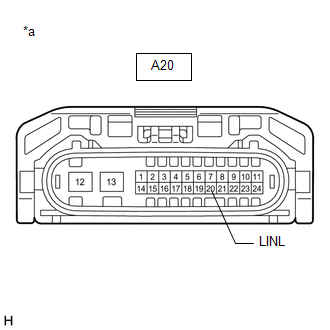
| *a | Front view of wire harness connector (to Headlight ECU Sub-assembly RH) |
(a) Disconnect the headlight ECU sub-assembly RH connector.
(b) Using the Techstream, check the waveform.
OK:
| Tester Connection | Switch Condition | Specified Condition |
|---|---|---|
| A20-20 (LINL) - Body ground | Power switch on (IG) | Pulse generation |
| NG | | REPLACE HEADLIGHT ECU SUB-ASSEMBLY LH |
|
| 9. | CHECK HEADLIGHT ECU SUB-ASSEMBLY RH |
(a) Remove the headlight ECU sub-assembly RH as a unit with the connectors still connected.
Click here
(b) Disconnect the A19 headlight ECU sub-assembly LH connector.
(c) Measure the resistance according to the value(s) in the table below.
Standard Resistance:
| Tester Connection | Condition | Specified Condition |
|---|---|---|
| A19-20 (LINL) - C-13 | Always | Below 1 Ω |
| OK | | REPLACE HEADLIGHT UNIT ASSEMBLY RH |
| NG | | REPLACE HEADLIGHT ECU SUB-ASSEMBLY RH |
READ NEXT:
 Initialization has not been Performed (B2450)
DESCRIPTION The vehicle height must be initialized for the headlight ECU sub-assembly LH to perform auto leveling control. DTC No. Detection Item DTC Detection Condition Trouble Area B245
Height Control Sensor Data Out of Range When Initializing (B2452)
DESCRIPTION The headlight ECU sub-assembly LH stores this DTC if the value from the rear height control sensor sub-assembly LH is out of range when performing initialization of the headlight ECU sub-a
Automatic High Beam Main Switch
InspectionINSPECTION PROCEDURE 1. INSPECT COMBINATION SWITCH ASSEMBLY (AUTOMATIC HIGH BEAM MAIN SWITCH) (a) Remove the combination switch assembly. Click here (b) Inspect the automatic high beam ma
SEE MORE:
Components
COMPONENTS ILLUSTRATION *1 DECK FLOOR BOX LH *2 REAR DECK FLOOR BOX *3 UPPER INSTRUMENT PANEL *4 AUXILIARY BATTERY NEGATIVE TERMINAL N*m (kgf*cm, ft.*lbf): Specified torque - - ILLUSTRATION *1 INSTRUMENT PANEL PASSENGER AIRBAG ASSEMBLY *2 NO. 2 INSTRUMENT
Odo/Trip Switch Malfunction
DESCRIPTION The ODO/TRIP display of the combination meter changes each time the trip switch is pressed. WIRING DIAGRAM CAUTION / NOTICE / HINT NOTICE: When replacing the combination meter assembly, make sure to replace it with a new one. PROCEDURE 1. READ VALUE USING TECHSTREAM (ODO/TRIP CHAN
