Lexus NX: Horn Circuit
DESCRIPTION
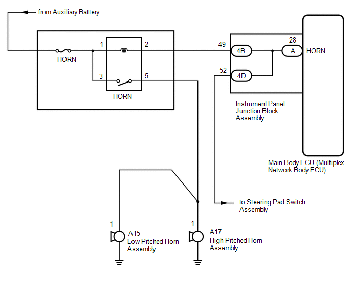
When the theft deterrent system is switched from the armed state to the alarm sounding state, the main body ECU (multiplex network body ECU) transmits a signal to cause the horn to sound at intervals of 0.4 seconds.
WIRING DIAGRAM
CAUTION / NOTICE / HINT
NOTICE:
Inspect the fuses for circuits related to this system before performing the following inspection procedure.
NOTICE:
- Inspect the fuses for circuits related to this system before performing the following inspection procedure.
-
If the main body ECU (multiplex network body ECU) is replaced, refer to Registration.
Click here
.gif)
PROCEDURE
| 1. | CHECK HORNS OPERATION |
(a) Press the horn switch and check if the horns sound.
| Horns do not sound | .gif) | GO TO HORN SYSTEM |
|
.gif)
| 2. | INSPECT INSTRUMENT PANEL JUNCTION BLOCK ASSEMBLY |
(a) Remove the instrument panel junction block assembly.
(b) Measure the resistance according to the value(s) in the table below.
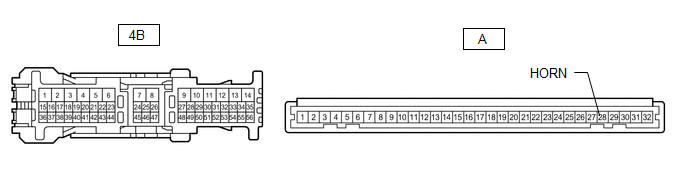
Standard Resistance:
| Tester Connection | Condition | Specified Condition |
|---|---|---|
| 4B-49 - A-28 (HORN) | Always | Below 1 Ω |
| OK | | REPLACE MAIN BODY ECU (MULTIPLEX NETWORK BODY ECU) |
| NG | | REPLACE INSTRUMENT PANEL JUNCTION BLOCK ASSEMBLY |
READ NEXT:
 Security Horn Circuit
DESCRIPTION When the theft deterrent system is switched from the armed state to the alarm sounding state, the main body ECU (multiplex network body ECU) transmits a signal to cause the security horn t
Theft Warning Siren Circuit
DESCRIPTION The theft warning siren has an internal battery. If the vehicle auxiliary battery cable is disconnected or any of the communication lines are open, the theft warning siren detects this and
SEE MORE:
Rear Power Window RH does not Operate with Rear Power Window Switch RH
DESCRIPTION When the power switch is on (IG), the rear power window regulator motor assembly RH is operated by the rear power window regulator switch assembly (for rear RH door). The rear power window regulator motor assembly RH has motor, regulator and ECU functions. WIRING DIAGRAM CAUTION / NOTIC
Throttle Pedal Position Sensor / Switch "A" Circuit (P0120-P0123,P0220,P0222,P0223,P2135)
DESCRIPTION HINT: These DTCs relate to the throttle position sensor. The throttle position sensor is mounted on the throttle body with motor assembly and detects the opening angle of the throttle valve. This sensor is a non-contact type sensor. It uses Hall-effect elements in order to yield accurate
