Lexus NX: IG2 Signal Malfunction (B2788)
DESCRIPTION
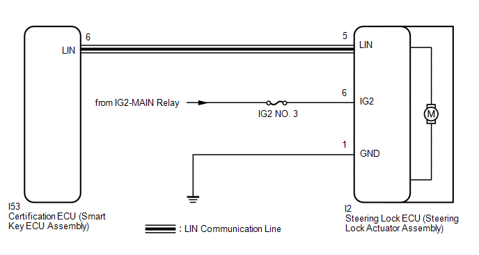
This DTC is stored when the steering lock ECU (steering lock actuator assembly) detects an IG2 power supply malfunction.
HINT:
The steering lock ECU (steering lock actuator assembly) is not connected to the CAN communication system. However, the steering lock ECU (steering lock actuator assembly) is connected to the certification ECU (smart key ECU assembly) via LIN communication and communicates with other components via CAN communication through the certification ECU (smart key ECU assembly).
| DTC No. | Detection Item | DTC Detection Condition | Trouble Area | Note |
|---|---|---|---|---|
| B2788 | IG2 Signal Malfunction | Mismatch between the steering lock ECU (steering lock actuator assembly) IG2 input from the LIN communication system and from the direct line (1-trip detection logic*). |
| DTC Output Confirmation Operation: No confirmation operation is necessary (monitoring is continuous). |
- *: Only output while a malfunction is present and the power switch is on (IG).
| Vehicle Condition when Malfunction Detected | Fail-safe Function when Malfunction Detected |
|---|---|
| The steering cannot be locked or unlocked. For this reason, the hybrid control system cannot be started. | - |
| DTC No. | Data List Item | Active Test Item |
|---|---|---|
| B2788 | - | - |
WIRING DIAGRAM
CAUTION / NOTICE / HINT
NOTICE:
- When using the Techstream with the power switch off, connect the Techstream to the vehicle and turn a courtesy light switch on and off at intervals of 1.5 seconds or less until communication between the Techstream and the vehicle begins. Then select the vehicle type under manual mode and enter the following menus: Body Electrical / Smart Access. While using the Techstream, periodically turn a courtesy light switch on and off at intervals of 1.5 seconds or less to maintain communication between the Techstream and the vehicle.
-
The steering lock system uses LIN communication. First perform the inspections in "How to Proceed with Troubleshooting" to confirm that there are no communication malfunctions before proceeding with troubleshooting.
Click here
.gif)
- Inspect the fuses for circuits related to this system before performing the following procedure.
-
After performing repairs, confirm that no DTCs are output again.
Click here
-
When replacing the steering lock ECU (steering lock actuator assembly), registration must be performed.
Click here
PROCEDURE
| 1. | INSPECT STEERING LOCK ECU (STEERING LOCK ACTUATOR ASSEMBLY) (POWER SOURCE MODE SIGNAL) |
(a) Make sure that there is no looseness at the locking part and the connecting part of the connector.
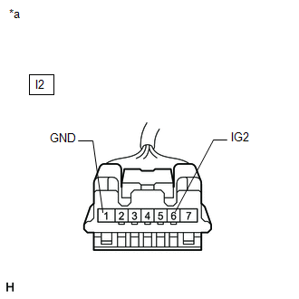
(b) Disconnect the I2 steering lock ECU (steering lock actuator assembly) connector.
| (c) Measure the resistance according to the value(s) in the table below. Standard Resistance:
|
|
(d) Measure the voltage according to the value(s) in the table below.
Standard Voltage:
| Tester Connection | Condition | Specified Condition |
|---|---|---|
| I2-6 (IG2) - I2-1 (GND) | Power switch on (IG) | 11 to 14 V |
| I2-6 (IG2) - I2-1 (GND) | Power switch off | Below 1 V |
| Result | Proceed to |
|---|---|
| OK (for Manual tilt and manual telescopic steering column) | A |
| OK (for Power tilt and power telescopic steering column) | B |
| NG | C |
| A | .gif) | REPLACE STEERING LOCK ECU (STEERING LOCK ACTUATOR ASSEMBLY) |
| B | | REPLACE STEERING LOCK ECU (STEERING LOCK ACTUATOR ASSEMBLY) |
| C | | REPAIR OR REPLACE HARNESS OR CONNECTOR |
READ NEXT:
 Unable to Unlock Steering Wheel (Hybrid Control System cannot Start)
DESCRIPTION The steering lock actuator assembly activates the steering lock motor and moves the lock bar into the steering column to lock the steering. The steering may not unlock when the lock bar ge
Steering Lock does not Lock
DESCRIPTION The steering lock actuator assembly activates the steering lock motor and moves the lock bar into the steering column to lock the steering. When the steering lock is operating, the steerin
SEE MORE:
Components
COMPONENTS ILLUSTRATION *A for 8 Inch Display *B for 10.3 Inch Display *1 CENTER INSTRUMENT CLUSTER FINISH PANEL ASSEMBLY *2 CONSOLE ARMREST ASSEMBLY *3 INSTRUMENT CLUSTER FINISH PANEL SUB-ASSEMBLY *4 INSTRUMENT PANEL FINISH PLATE *5 INSTRUMENT SIDE PANEL LH *6
Removal
REMOVAL PROCEDURE 1. REMOVE NO. 1 ENGINE UNDER COVER ASSEMBLY Click here 2. REMOVE FAN AND GENERATOR V BELT Click here 3. REMOVE FRONT SUSPENSION MEMBER REINFORCEMENT RH Click here 4. REMOVE CRANKSHAFT PULLEY ASSEMBLY Click here 5. REMOVE TIMING CHAIN COVER OIL SEAL (a) Using a screwdri
