Lexus NX: Inspection
INSPECTION
PROCEDURE
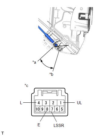
1. INSPECT FRONT DOOR LOCK ASSEMBLY LH
| (a) Check the door lock motor operation. (1) Apply auxiliary battery voltage to the motor connector and check the operation of the door lock motor. OK:
If the result is not as specified, replace the front door lock assembly LH. |
|
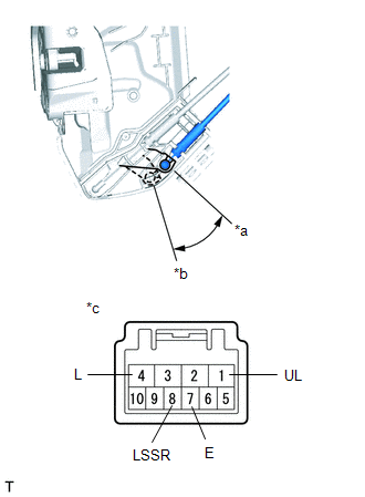
(b) Check the operation of the door unlock detection switch.
(1) Measure the resistance according to the value(s) in the table below.
Standard Resistance:
| Tester Connection | Condition | Specified Condition |
|---|---|---|
| 7 (E) - 8 (LSSR) | Lock | 10 kΩ or higher |
| Unlock | Below 1 Ω |
If the result is not as specified, replace the front door lock assembly LH.
| (c) Check the resistance of the lock and unlock switch. (1) Measure the resistance according to the value(s) in the table below. Standard Resistance:
If the result is not as specified, replace the front door lock assembly LH. |
|
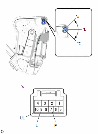
2. INSPECT FRONT DOOR LOCK ASSEMBLY RH
| (a) Check the door lock motor operation. (1) Apply auxiliary battery voltage to the motor connector and check the operation of the door lock motor. OK:
If the result is not as specified, replace the front door lock assembly RH. |
|
(b) Check the operation of the door unlock detection switch.
(1) Measure the resistance according to the value(s) in the table below.
Standard Resistance:
| Tester Connection | Condition | Specified Condition |
|---|---|---|
| 7 (LSSR) - 8 (E) | Lock | 10 kΩ or higher |
| 7 (LSSR) - 8 (E) | Unlock | Below 1 Ω |
If the result is not as specified, replace the front door lock assembly RH.
READ NEXT:
 Installation
INSTALLATION CAUTION / NOTICE / HINT HINT:
Use the same procedure for the RH and LH sides.
The procedure listed below is for the LH side.
A bolt without a torque specification is shown in the s
Precaution
PRECAUTION PRECAUTIONS WHEN USING TECHSTREAM (a) When using the Techstream with the vehicle power switch off, connect the Techstream to the DLC3 and turn a courtesy light switch on and off at interval
SEE MORE:
Hazard Warning Switch Circuit
DESCRIPTION When the combination meter receives a hazard warning signal switch signal, the flasher IC turns on and hazard control is performed. WIRING DIAGRAM CAUTION / NOTICE / HINT NOTICE: When replacing the combination meter assembly, make sure to replace it with a new one. PROCEDURE 1. RE
Parts Location
PARTS LOCATION ILLUSTRATION *1 FORWARD RECOGNITION CAMERA *2 MILLIMETER WAVE RADAR SENSOR ASSEMBLY *3 BRAKE BOOSTER WITH MASTER CYLINDER ASSEMBLY - SKID CONTROL ECU *4 PARKING BRAKE ECU ASSEMBLY ILLUSTRATION *1 STEERING PAD SWITCH ASSEMBLY - VEHICLE-TO-VEHICLE DISTANCE C
