Lexus NX: Inspection
INSPECTION
PROCEDURE
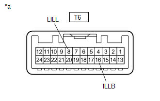
1. INSPECT MAP LIGHT ASSEMBLY (PERSONAL LIGHT)
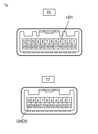
| (a) Inspect the front map light. (1) Apply battery voltage to the connector and check the light illumination condition. OK:
If the result is not as specified, replace the map light assembly (personal light). |
|
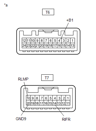
| (b) Inspect the front dome light. (1) Apply battery voltage to the connector and check the light illumination condition. OK:
If the result is not as specified, replace the map light assembly (personal light). |
|
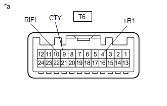
| (c) Inspect internal circuit. (1) Measure the resistance according to the value(s) in the table below. Standard Resistance:
If the result is not as specified, replace the map light assembly (personal light). |
|
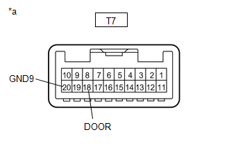
| (d) Inspect the door switch. (1) Measure the resistance according to the value(s) in the table below. Standard Resistance:
If the result is not as specified, replace the map light assembly (personal light). |
|
| (e) Inspect the switch illumination. (1) Apply battery voltage to the connector and check the light illumination condition. OK:
If the result is not as specified, replace the map light assembly (personal light). |
|
READ NEXT:
 Reassembly
REASSEMBLY PROCEDURE 1. INSTALL MAP LIGHT SUB-ASSEMBLY (a) Attach the 17 claws to install the map light sub-assembly.
Installation
INSTALLATION PROCEDURE 1. INSTALL MAP LIGHT ASSEMBLY (PERSONAL LIGHT) (a) Connect the connectors. (b) Attach the 4 clips to install the map light assembly (personal light).
Rear Door Courtesy Switch
ComponentsCOMPONENTS ILLUSTRATION *1 REAR DOOR COURTESY LIGHT SWITCH ASSEMBLY - - N*m (kgf*cm, ft.*lbf): Specified torque - - RemovalREMOVAL CAUTION / NOTICE / HINT HINT:
SEE MORE:
Installation
INSTALLATION PROCEDURE 1. INSTALL FUEL PUMP CONTROL ECU ASSEMBLY Click here 2. INSTALL PARKING BRAKE ECU ASSEMBLY (a) Install the parking brake ECU assembly with the 2 bolts. Torque: 8.0 N·m {82 kgf·cm, 71 in·lbf} (b) Connect the 3 connectors. 3. INSTALL DECK TRIM SIDE PANEL ASSEMBLY LH Click
Installation
INSTALLATION PROCEDURE 1. INSTALL INTEGRATION CONTROL AND PANEL ASSEMBLY (a) Install the integration control and panel assembly to the rear upper console panel sub-assembly with the 2 screws. HINT: The locations labeled A in the illustration are tightened together with the shift position indicato
