Lexus NX: Installation
INSTALLATION
CAUTION / NOTICE / HINT
HINT:
Perform "Inspection After Repair" after replacing the EGR valve assembly.
Click here .gif)
PROCEDURE
1. INSTALL EGR VALVE ASSEMBLY
HINT:
Perform "Inspection After Repair" after replacing the EGR valve assembly.
Click here
| (a) Install 2 new gaskets to the No. 1 EGR pipe and intake manifold. NOTICE: Make sure that the gasket is installed in the correct direction. |
|
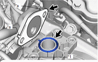
(b) Temporarily install the EGR valve assembly to the intake manifold with the 3 bolts.
(c) Connect the No. 1 EGR pipe to the EGR valve assembly and temporarily install the 2 nuts.
(d) Tighten the 3 bolts.
Torque:
10 N·m {102 kgf·cm, 7 ft·lbf}
(e) Using a 12 mm deep socket wrench, tighten the 2 nuts.
Torque:
21 N·m {214 kgf·cm, 15 ft·lbf}
(f) Using a 10 mm deep socket wrench, install the engine cover joint to the EGR valve assembly.
Torque:
10 N·m {102 kgf·cm, 7 ft·lbf}
(g) Connect the No. 1 water by-pass hose and No. 2 water by-pass hose to the EGR valve assembly, and slide the 2 clamps to secure the hose.
(h) Connect the connector to the EGR valve assembly.
2. INSTALL AIR CLEANER CAP AND HOSE
Click here
3. INSTALL NO. 1 ENGINE COVER SUB-ASSEMBLY
Click here
4. ADD ENGINE COOLANT
Click here
5. INSPECT FOR COOLANT LEAK
Click here
READ NEXT:
 Parts Location
PARTS LOCATION ILLUSTRATION *1 AIR FUEL RATIO SENSOR (for Bank 1 Sensor 1) *2 CHARCOAL CANISTER ASSEMBLY *3 EGR VALVE ASSEMBLY *4 FUEL TANK CAP ASSEMBLY *5 HEATED OXYGEN SENS
System Diagram
SYSTEM DIAGRAM *1 ECM *2 Engine Coolant Temperature Sensor *3 Air Fuel Ratio Sensor (for Bank 1 Sensor 1) *4 Heated Oxygen Sensor (for Bank 1 Sensor 2) *5 Crankshaft Position
SEE MORE:
Speedometer Malfunction
DESCRIPTION The combination meter assembly receives vehicle speed signals from the brake booster with master cylinder assembly (skid control ECU) via the CAN communication line. The wheel speed sensors output voltages that vary according to the vehicle speed. The brake booster with master cylinder a
How To Proceed With Troubleshooting
CAUTION / NOTICE / HINT HINT: Use these procedures to troubleshoot the adaptive variable suspension system. *: Use the Techstream. PROCEDURE 1. VEHICLE BROUGHT TO WORKSHOP
NEXT 2. PROBLEM SYMPTOM CONFIRMATION
NEXT 3. INSPECT AUXILIARY BATTERY
