Lexus NX: Installation
INSTALLATION
PROCEDURE
1. INSTALL NO. 2 EXHAUST MANIFOLD HEAT INSULATOR
(a) Install the No. 2 exhaust manifold heat insulator with the 2 bolts.
Torque:
13.5 N·m {138 kgf·cm, 10 ft·lbf}
2. INSTALL EXHAUST MANIFOLD CONVERTER SUB-ASSEMBLY
(a) Install a new exhaust manifold to head gasket to the cylinder head sub-assembly.
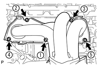
(b) Temporarily install the exhaust manifold converter sub-assembly with the 5 nuts.
(c) Temporarily install the manifold stay and No. 2 manifold stay with the 2 bolts and 2 nuts.
| (d) Tighten the 5 nuts in the order shown in the illustration. Torque: 35 N·m {357 kgf·cm, 26 ft·lbf} |
|
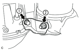
3. INSTALL MANIFOLD STAY
| (a) Tighten the bolt and nut in the order shown in the illustration. Torque: 43 N·m {438 kgf·cm, 32 ft·lbf} |
|
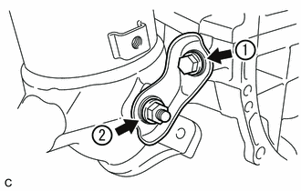
4. INSTALL NO. 2 MANIFOLD STAY
| (a) Tighten the bolt and nut in the order shown in the illustration. Torque: 43 N·m {438 kgf·cm, 32 ft·lbf} |
|
5. INSTALL NO. 2 EGR PIPE
(a) Install 2 new gaskets to the No. 2 EGR pipe.
NOTICE:
Make sure the claws of the gasket face the No. 2 EGR pipe.
(b) Install the No. 2 EGR pipe with the 2 bolts and 2 nuts.
Torque:
36 N·m {367 kgf·cm, 27 ft·lbf}
6. INSTALL NO. 1 MANIFOLD CONVERTER INSULATOR
(a) Install the No. 1 manifold converter insulator with the 3 bolts.
Torque:
13.5 N·m {138 kgf·cm, 10 ft·lbf}
7. INSTALL AIR FUEL RATIO SENSOR
Click here .gif)
8. CONNECT INVERTER RESERVOIR ASSEMBLY
Click here
9. CONNECT WIRE HARNESS
Click here
10. INSTALL NO. 1 EXHAUST MANIFOLD HEAT INSULATOR
(a) Install the No. 1 exhaust manifold heat insulator with the 4 bolts.
Torque:
12 N·m {122 kgf·cm, 9 ft·lbf}
11. INSTALL FRONT EXHAUST PIPE ASSEMBLY
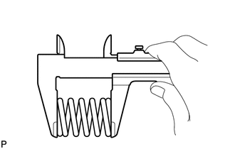
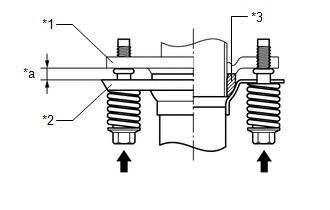
| (a) Using a vernier caliper, measure the free length of the compression spring. Minimum length: 41.5 mm (1.63 in.) If the length is less than the minimum, replace the compression spring. |
|
(b) Using a wire brush, remove any foreign matter from the gasket installation surface.
| (c) Using a plastic-faced hammer and wooden block, tap in a new gasket until its surface is flush with the exhaust manifold converter sub-assembly. NOTICE:
|
|
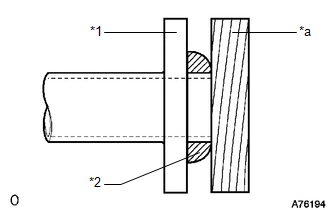
(d) Install a new gasket to the front exhaust pipe assembly.
| (e) Install the front exhaust pipe assembly with the 2 compression springs and 4 bolts. Torque: 43 N·m {438 kgf·cm, 32 ft·lbf} HINT: After installation, check that the space between the flanges of the exhaust manifold converter sub-assembly and front exhaust pipe assembly is consistent front-to-rear and left-to-right. |
|
(f) Connect the heated oxygen sensor connector.
12. INSTALL NO. 1 ENGINE UNDER COVER ASSEMBLY
Click here
13. INSTALL NO. 1 ENGINE COVER SUB-ASSEMBLY
Click here
14. INSPECT FOR EXHAUST GAS LEAK
Click here
READ NEXT:
 Components
COMPONENTS ILLUSTRATION *1 CENTER EXHAUST PIPE ASSEMBLY *2 EXHAUST PIPE DAMPER *3 FRONT EXHAUST PIPE ASSEMBLY *4 HEATED OXYGEN SENSOR *5 TAIL EXHAUST PIPE ASSEMBLY *6 EXH
Removal
REMOVAL CAUTION / NOTICE / HINT CAUTION:
Wear protective gloves when removing the exhaust pipe assembly.
The exhaust pipe assembly is extremely hot immediately after the engine has stopped.
Con
SEE MORE:
Inspection
INSPECTION PROCEDURE 1. INSPECT REAR LIGHT ASSEMBLY LH (a) Apply battery voltage to the connector and check the light illumination condition. OK: Battery Connection Specified Condition Positive (+) → 2 (B) Negative (-) → 4 (E) Taillight illuminates Positive (+) → 3 (B) Negat
Only Back Door cannot be Opened
DESCRIPTION The main body ECU (multiplex network body ECU) receives signals from the back door opener switch assembly. Then, the main body ECU (multiplex network body ECU) activates the back door lock motor. WIRING DIAGRAM CAUTION / NOTICE / HINT NOTICE:
When using the Techstream with the vehicl
