Lexus NX: Installation
INSTALLATION
PROCEDURE
1. INSTALL POWER STEERING ECU ASSEMBLY
(a) Install a new electric power steering motor shaft damper to the power steering ECU assembly.
(b) Install a new electric power steering motor shaft spacer to the power steering ECU assembly.
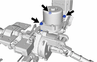
| (c) Temporarily install the power steering ECU assembly to the electric power steering column sub-assembly with the 3 bolts. NOTICE: Do not tighten the bolts until the heads contact the surface of the power steering ECU assembly. Leave a small amount of clearance so that the power steering ECU assembly can be centered in a later procedure. |
|
(d) Remove the No. 2 steering intermediate shaft assembly from the electric power steering column sub-assembly.
| (e) Secure the electric power steering column sub-assembly in a vise between aluminum plates or pieces of cloth as shown in the illustration. NOTICE:
|
|
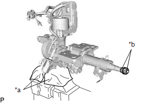
(f) Install the 2 nuts to the electric power steering column sub-assembly.
HINT:
The nuts to use are the steering wheel set nut or equivalents.
| Steering wheel set nut part No. | Thread diameter | Thread pitch |
|---|---|---|
| 90179-12071 | 12 mm (0.4724 in.) | 1.25 mm (0.0492 in.) |
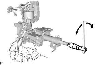
| (g) Turn the steering main shaft by 180° to the left and right at a speed of 1 turn per second. Repeat these movements 2 to 3 times to center the power steering ECU assembly. |
|
(h) Tighten the 3 bolts.
Torque:
18.5 N·m {189 kgf·cm, 14 ft·lbf}
| (i) Check the turning torque of the steering main shaft. Standard preload: 0.9 to 1.5 N*m (10 to 15 kgf*cm, 8 to 13 in.*lbf) NOTICE: Make sure that the shaft turns smoothly. HINT: If the result is not as specified, center the power steering ECU assembly again. |
|
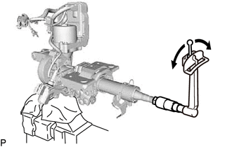
(j) Install the No. 2 steering intermediate shaft assembly to the electric power steering column sub-assembly.
Torque:
35.3 N·m {360 kgf·cm, 26 ft·lbf}
(k) Connect the 2 connector clamps of a new ECU wire harness sub-assembly to the harness bracket.
(l) Connect the 3 connectors to the power steering ECU assembly.
(m) Install the 2 cable ties and heat resistant tape.
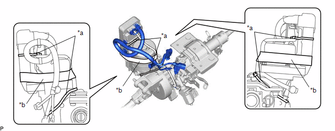
| *a | Cable Tie | *b | Heat Resistant Tape |
NOTICE:
As heat from the power steering motor assembly may generate smoke, use heat resistant tape (resistant to 100°C (212°F) or higher).
(n) Install a new power steering ECU protector to the power steering ECU assembly.
2. INSTALL ELECTRIC POWER STEERING COLUMN SUB-ASSEMBLY
Click here .gif)
3. PERFORM TORQUE SENSOR ZERO POINT CALIBRATION
Click here
4. PERFORM ASSIST MAP WRITING
Click here
READ NEXT:
 Precaution
PRECAUTION HANDLING PRECAUTIONS FOR SRS AIRBAG SYSTEM (a) This vehicle is equipped with a Supplemental Restraint System (SRS). Failure to carry out service operations in the correct sequence could cau
Parts Location
PARTS LOCATION ILLUSTRATION *1 POWER STEERING ECU ASSEMBLY *2 ELECTRIC POWER STEERING COLUMN SUB-ASSEMBLY - POWER STEERING MOTOR ASSEMBLY - MOTOR ROTATION ANGLE SENSOR - TORQUE SENSOR - ECU
SEE MORE:
NTSC Disconnected (from Park Assist/Monitoring ECU) (B1535,C1622)
DESCRIPTION This DTC is stored if the radio receiver assembly judges that the signals or signal lines between the television camera assembly and the multi-display assembly are not normal as a result of its self check. DTC No. Detection Item DTC Detection Condition Trouble Area B1535 N
Tires
Replace or rotate tires in accordance
with maintenance schedules
and treadwear.
Checking tires
Check if the treadwear indicators are
showing on the tires. Also check the
tires for uneven wear, such as excessive
wear on one side of the tread.
Check the spare tire condition and
pressure if
