Lexus NX: Installation
INSTALLATION
CAUTION / NOTICE / HINT
HINT:
- Use the same procedure for the RH and LH sides.
- The procedure listed below is for the LH side.
PROCEDURE
1. INSTALL SIDE MUDGUARD SUB-ASSEMBLY LH
HINT:
When installing the side mudguard sub-assembly LH, heat the vehicle body and side mudguard sub-assembly LH using a heat light.
Standard:
| Item | Temperature |
|---|---|
| Vehicle Body | 40 to 60°C (104 to 140°F) |
| Side Mudguard Sub-assembly LH | 20 to 30°C (68 to 86°F) |
NOTICE:
Do not heat the vehicle body or side mudguard sub-assembly LH excessively.
(a) Clean the vehicle body surface.
(1) Using a heat light, heat the vehicle body surface.
(2) Remove the double-sided tape from the back door panel.
(3) Wipe off any tape adhesive residue with cleaner.
(b) Install the side mudguard sub-assembly LH.
(1) Using a heat light, heat the vehicle body.
(2) Remove the peeling paper from the face of the No. 3 moulding tape.
HINT:
After removing the peeling paper, keep the exposed adhesive free from foreign matter.
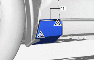
| (3) Attach the 2 clips so as to apply the No. 3 moulding tape and install the side mudguard sub-assembly LH as shown in the illustration. HINT: Press the side mudguard sub-assembly LH firmly to install it. |
|
(c) Install a new grommet.
(d) Install the clip.
(e) Install the screw.
READ NEXT:
 Components
COMPONENTS ILLUSTRATION *1 FRONT FENDER MOULDING SUB-ASSEMBLY LH - - ILLUSTRATION *1 NO. 1 MOULDING TAPE *2 NO. 2 MOULDING TAPE ● Non-reusable part - -
Removal
REMOVAL CAUTION / NOTICE / HINT HINT:
Use the same procedure for the RH and LH sides.
The procedure listed below is for the LH side.
PROCEDURE 1. REMOVE FRONT FENDER MOULDING SUB-ASSEMBLY LH H
SEE MORE:
Inspection
INSPECTION PROCEDURE 1. INSPECT SEPARATE TYPE FRONT SEATBACK COVER LH *a Component without harness connected (Separate Type Front Seatback Cover LH (Front Seatback Heater)) (a) Check the separate type front seatback cover LH (front seatback heater). (1) Measure the resistance according to t
Remote Service Malfunction
PROCEDURE 1. CHECK CAN COMMUNICATION SYSTEM (a) Connect the Techstream to the DLC3. (b) Turn the power switch on (IG). (c) Turn the Techstream on. (d) Enter the following menus: Bus Check. Click here (e) Check that all ECUs and sensors that use CAN communication are connected. Result
