Lexus NX: Removal
REMOVAL
CAUTION / NOTICE / HINT
HINT:
- Use the same procedure for the RH and LH sides.
- The procedure listed below is for the LH side.
PROCEDURE
1. REMOVE FRONT FENDER MOULDING SUB-ASSEMBLY LH
HINT:
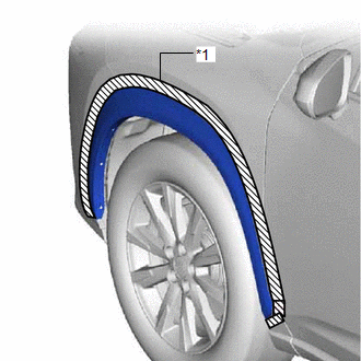
When removing the front fender moulding sub-assembly LH, if the No. 1 moulding tape (double-sided tape) and No. 2 moulding tape (double-sided tape) is difficult to remove, heat the adhesive of the front fender moulding sub-assembly LH using a heat light.
Standard:
| Item | Temperature |
|---|---|
| Front Fender Moulding Sub-assembly LH | 40 to 60°C (104 to 140°F) |
NOTICE:
Do not heat the front fender moulding sub-assembly LH excessively.
| (a) Remove the 6 clips. |
|
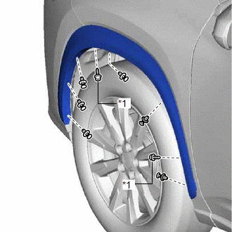
(b) Using a 4 mm hexagon socket wrench, remove the 2 hexagon screws.
| (c) Put protective tape around the front fender moulding sub-assembly LH. |
|
(d) Fold back part of the front fender liner LH as shown in the illustration, and detach the 5 claws on the back of the front fender moulding sub-assembly LH.
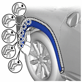
.png) | Direction to Press Claws |
(e) Detach the 8 clips, No. 1 moulding tape (double-sided tape) and No. 2 moulding tape (double-sided tape) in order starting from the front of the vehicle to remove the front fender moulding sub-assembly LH.
NOTICE:
Press down on the area labeled A in the illustration to make sure the front bumper cover is not damaged.
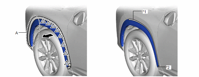
| *1 | No. 1 Moulding Tape (Double-sided Tape) | *2 | No. 2 Moulding Tape (Double-sided Tape) |
| | Direction to Pull | - | - |
READ NEXT:
 Disassembly
DISASSEMBLY CAUTION / NOTICE / HINT HINT:
Use the same procedure for the RH and LH sides.
The procedure listed below is for the LH side.
PROCEDURE 1. REMOVE NO. 1 MOULDING TAPE (a) Remove the
Reassembly
REASSEMBLY CAUTION / NOTICE / HINT HINT:
Use the same procedure for the RH and LH sides.
The procedure listed below is for the LH side.
PROCEDURE 1. INSTALL NO. 1 MOULDING TAPE (a) Clean the N
Installation
INSTALLATION CAUTION / NOTICE / HINT HINT:
Use the same procedure for the RH and LH sides.
The procedure listed below is for the LH side.
PROCEDURE 1. INSTALL FRONT FENDER MOULDING SUB-ASSEMBL
SEE MORE:
Operation History List
OPERATION HISTORY LIST NOTICE:
The cause of a malfunction is stored in the RAM or EEPROM in the certification ECU (smart key ECU assembly). As the cause of a malfunction stored in the RAM will be cleared when the cable is disconnected from the negative (-) auxiliary battery terminal, do not disco
Components
COMPONENTS ILLUSTRATION *1 CRUISE CONTROL MAIN SWITCH *2 STEERING PAD SWITCH ASSEMBLY
