Lexus NX: Installation
INSTALLATION
CAUTION / NOTICE / HINT
HINT:
- Use the same procedure for the RH and LH sides.
- The procedure listed below is for the LH side.
PROCEDURE
1. INSTALL FRONT FENDER MOULDING SUB-ASSEMBLY LH
HINT:
When installing the front fender moulding sub-assembly LH, heat the vehicle body and front fender moulding sub-assembly LH using a heat light.
Standard:
| Item | Temperature |
|---|---|
| Vehicle Body | 40 to 60°C (104 to 140°F) |
| Front Fender Moulding Sub-assembly LH | 20 to 30°C (68 to 86°F) |
NOTICE:
Do not heat the vehicle body and front fender moulding sub-assembly LH excessively.
(a) Clean the vehicle body surface.
(1) Using a heat light, heat the vehicle body surface.
(2) Remove the double-sided tape from the vehicle body.
(3) Wipe off any tape adhesive residue with cleaner.
(b) Install the front fender moulding sub-assembly LH.
(1) Using a heat light, heat the vehicle body.
(2) Remove the peeling paper from the face of the No. 1 moulding tape and No. 5 moulding tape.
HINT:
After removing the peeling paper, keep the exposed adhesive free from foreign matter.
(c) Attach the 5 claws and 8 clips so as to apply the No. 1 moulding tape and No. 2 moulding tape and install the front fender moulding sub-assembly LH as shown in the illustration.
HINT:
Press the front fender moulding sub-assembly LH firmly to install it.
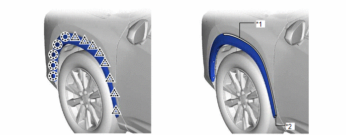
| *1 | No. 1 Moulding Tape (Double-sided Tape) | *2 | No. 2 Moulding Tape (Double-sided Tape) |
(d) Using a 4 mm hexagon socket wrench, install the 2 hexagon screws.
(e) Install the 6 clips.
READ NEXT:
 Components
COMPONENTS ILLUSTRATION *1 QUARTER OUTSIDE MOULDING SUB-ASSEMBLY LH - - ILLUSTRATION *1 NO. 5 MOULDING TAPE *2 REAR LOWER QUARTER MOULDING PROTECTOR LH ● Non-reusable pa
Removal
REMOVAL CAUTION / NOTICE / HINT HINT:
Use the same procedure for the RH and LH sides.
The procedure listed below is for the LH side.
PROCEDURE 1. REMOVE QUARTER OUTSIDE MOULDING SUB-ASSEMBLY L
SEE MORE:
ECU Malfunction (C1611)
DESCRIPTION If the clearance warning ECU assembly detects an internal malfunction during self-diagnosis, DTC C1611 is stored. DTC No. Detection Item DTC Detection Condition Trouble Area C1611 ECU Malfunction
Sub-CPU abnormal signal
Mirror check abnormal
Clearance warning E
Fail-safe Chart
FAIL-SAFE CHART If a problem occurs in the power steering system, the power steering assist will be stopped or the amount of power assist will be decreased to protect the system. Power Steering System Malfunction Fail-safe Operation Power steering warning light Buzzer
Torque sensor (
