Lexus NX: Removal
REMOVAL
CAUTION / NOTICE / HINT
HINT:
- Use the same procedure for the RH and LH sides.
- The procedure listed below is for the LH side.
PROCEDURE
1. REMOVE QUARTER OUTSIDE MOULDING SUB-ASSEMBLY LH
HINT:
When removing the quarter outside moulding sub-assembly LH, if the No. 5 moulding tape(double-sided tape) is difficult to remove, heat the adhesive of the quarter outside moulding sub-assembly LH using a heat light.
Standard:
| Item | Temperature |
|---|---|
| Quarter Outside Moulding Sub-assembly LH | 40 to 60°C (104 to 140°F) |
NOTICE:
Do not heat the quarter outside moulding sub-assembly LH excessively.
| (a) Remove the 3 clip. |
|
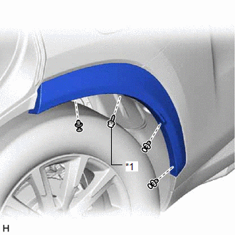
(b) Using a 4 mm hexagon socket wrench, remove the hexagon screw.
| (c) Put protective tape around the quarter outside moulding sub-assembly LH. |
|
(d) Detach the 3 clips and 4 claws and remove the quarter outside moulding sub-assembly LH.
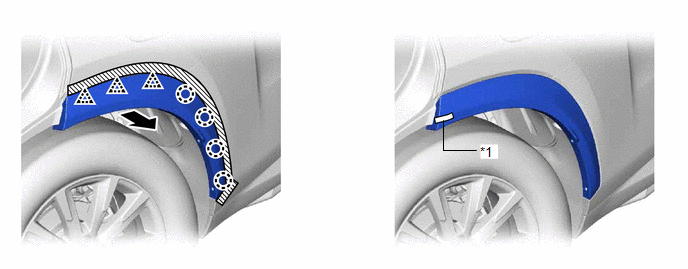
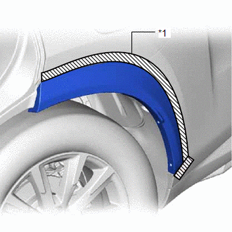
| *1 | No. 5 Moulding Tape (Double-sided Tape) | - | - |
.png) | Direction to Pull | - | - |
READ NEXT:
 Disassembly
DISASSEMBLY CAUTION / NOTICE / HINT HINT:
Use the same procedure for the RH and LH sides.
The procedure listed below is for the LH side.
PROCEDURE 1. REMOVE NO. 5 MOULDING TAPE (a) Remove the
Reassembly
REASSEMBLY CAUTION / NOTICE / HINT HINT:
Use the same procedure for the RH and LH sides.
The procedure listed below is for the LH side.
PROCEDURE 1. INSTALL NO. 5 MOULDING TAPE (a) Clean the N
Installation
INSTALLATION CAUTION / NOTICE / HINT PROCEDURE 1. INSTALL QUARTER OUTSIDE MOULDING SUB-ASSEMBLY LH HINT: When installing the quarter outside moulding sub-assembly LH, heat the vehicle body and quarter
SEE MORE:
Initialization
INITIALIZATION INITIALIZATION SERVO MOTOR (a) Turn the power switch off. (b) Connect the Techstream to the DLC3. (c) Turn the power switch on (IG). (d) Press the A/C OFF switch. (e) Turn the Techstream on. (f) Enter the following menus: Body Electrical / Air Conditioner / Utility / Servomotor Initia
Check Bus 2 Lines for Short Circuit
DESCRIPTION There may be a short circuit between the CAN main bus wire and/or CAN branch wire when the resistance between terminals 18 (CA4H) and 17 (CA4L) of the central gateway ECU (network gateway ECU) is below 54 Ω. Symptom Trouble Area
*1: w/ Headup Display
*2: w/ ASC System *3: for T
