Lexus NX: Installation
INSTALLATION
PROCEDURE
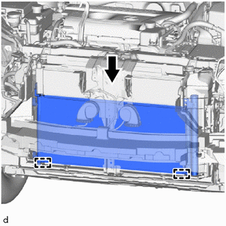
1. INSTALL COOLER CONDENSER ASSEMBLY
| (a) Attach the 2 guides to install the cooler condenser assembly. NOTICE: Do not damage the cooler condenser assembly or radiator assembly when installing the cooler condenser assembly. HINT: If the cooler condenser assembly is replaced with a new one, add compressor oil to the new cooler condenser assembly. Capacity: 40 cc (1.35 fl.oz) Compressor Oil: ND-OIL 11 or equivalent |
|
2. CONNECT LIQUID PIPE SUB-ASSEMBLY
(a) Remove the vinyl tape from the liquid pipe sub-assembly and the connecting part of the cooler condenser assembly.
(b) Sufficiently apply compressor oil to a new O-ring and the fitting surface of the liquid pipe sub-assembly.
Compressor Oil:
ND-OIL 11 or equivalent
(c) Install the O-ring to the liquid pipe sub-assembly.
NOTICE:
Keep the O-rings and O-ring fitting surfaces free of foreign matter.
(d) Connect the liquid pipe sub-assembly to the cooler condenser assembly with the bolt.
Torque:
5.4 N·m {55 kgf·cm, 48 in·lbf}
3. CONNECT DISCHARGE HOSE SUB-ASSEMBLY
(a) Remove the vinyl tape from the discharge hose sub-assembly and the connecting part of the cooler condenser assembly.
(b) Sufficiently apply compressor oil to a new O-ring and the fitting surface of the discharge hose sub-assembly.
Compressor Oil:
ND-OIL 11 or equivalent
(c) Install the O-ring to the discharge hose sub-assembly.
NOTICE:
Keep the O-rings and O-ring fitting surfaces free of foreign matter.
(d) Connect the discharge hose sub-assembly to the cooler condenser assembly with the bolt.
Torque:
5.4 N·m {55 kgf·cm, 48 in·lbf}
4. INSTALL RADIATOR ASSEMBLY
Click here .gif)
5. INSTALL FRONT BUMPER COVER
(a) for Sport Package:
Click here
(b) except Sport Package:
Click here
6. CHARGE AIR CONDITIONING SYSTEM WITH REFRIGERANT
Click here
7. WARM UP COMPRESSOR
Click here
8. INSPECT FOR REFRIGERANT LEAK
Click here
READ NEXT:
 Cooler Expansion Valve
ComponentsCOMPONENTS ILLUSTRATION *1 AIR CONDITIONER TUBE AND ACCESSORY ASSEMBLY *2 COOLER EXPANSION VALVE *3 O-RING - - N*m (kgf*cm, ft.*lbf): Specified torque ● Non
Front Blower Motor
ComponentsCOMPONENTS ILLUSTRATION *1 BLOWER WITH FAN MOTOR SUB-ASSEMBLY *2 NO. 2 INSTRUMENT PANEL UNDER COVER SUB-ASSEMBLY RemovalREMOVAL PROCEDURE 1. REMOVE NO. 2 INSTRUMENT PANEL UNDE
SEE MORE:
Components
COMPONENTS ILLUSTRATION *A w/ Woofer *B w/o Woofer *1 BACK DOOR CENTER GARNISH *2 BACK DOOR LOCK COVER *3 BACK DOOR SIDE GARNISH LH *4 BACK DOOR SIDE GARNISH RH *5 BACK DOOR TRIM BASE *6 BACK DOOR TRIM BOARD ASSEMBLY *7 POWER BACK DOOR WARNING BUZZER *
Parts Location
PARTS LOCATION ILLUSTRATION *1 FRONT DOOR COURTESY LIGHT SWITCH ASSEMBLY LH *2 SHIFT LEVER POSITION SENSOR *3 SIDE TURN SIGNAL LIGHT ASSEMBLY LH *4 SIDE TURN SIGNAL LIGHT ASSEMBLY RH *5 OUTER REAR VIEW MIRROR ASSEMBLY LH *6 OUTER REAR VIEW MIRROR ASSEMBLY RH *7 HE
