Lexus NX: Installation
INSTALLATION
PROCEDURE
1. INSTALL HEATER ACCESSORY ASSEMBLY
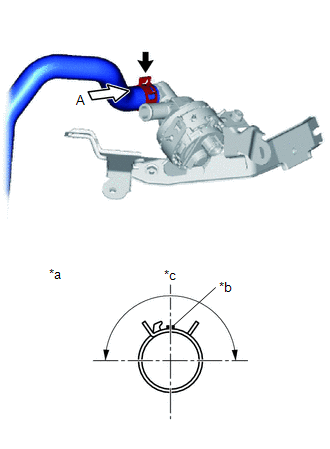
| (a) Connect the heater water inlet hose A with the paint mark (Blue) facing up and attach the clip within the area shown in the illustration. NOTICE: Do not apply excessive force to the heater water inlet hose A. |
|
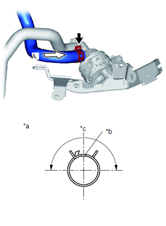
| (b) Connect the heater water outlet hose A with the indentation part facing up and attach the clip within the area shown in the illustration. NOTICE: Do not apply excessive force to the heater water outlet hose A. |
|
| (c) Temporarily install the heater water pump assembly (heater water pump) with the 3 bolts and nut. |
|
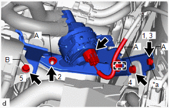
(d) Tighten the 3 bolts and nut in the order as shown in the illustration.
Torque:
Bolt A, Nut A :
9.8 N·m {100 kgf·cm, 87 in·lbf}
Bolt B :
7.7 N·m {79 kgf·cm, 68 in·lbf}
(e) Attach the clamp.
(f) Connect the connector.
2. INSTALL AIR CLEANER CASE SUB-ASSEMBLY
Click here .gif)
3. INSTALL AIR CLEANER FILTER ELEMENT SUB-ASSEMBLY
Click here
4. INSTALL AIR CLEANER CAP SUB-ASSEMBLY
Click here
5. ADD ENGINE COOLANT (for Inverter Coolant)
Click here
6. INSPECT FOR COOLANT LEAK (for Inverter Coolant)
Click here
READ NEXT:
 Components
COMPONENTS ILLUSTRATION *1 AIR CONDITIONING THERMISTOR ASSEMBLY (HUMIDITY SENSOR) *2 NO. 1 FORWARD RECOGNITION COVER *3 NO. 2 FORWARD RECOGNITION COVER *4 PROTECTOR
Removal
REMOVAL PROCEDURE 1. REMOVE NO. 2 FORWARD RECOGNITION COVER Click here 2. REMOVE NO. 1 FORWARD RECOGNITION COVER Click here 3. REMOVE PROTECTOR (a) Detach the 2 claws and remove the protector.
SEE MORE:
Removal
REMOVAL CAUTION / NOTICE / HINT HINT:
Use the same procedure for the RH and LH sides.
The procedure described below is for the LH side.
PROCEDURE 1. REMOVE REAR BUMPER ASSEMBLY Click here 2. REMOVE TONNEAU COVER ASSEMBLY Click here 3. REMOVE DECK BOARD ASSEMBLY Click here 4. REMOVE R
Fuel Pump Ecu
ComponentsCOMPONENTS ILLUSTRATION *1 FUEL PUMP CONTROL ECU ASSEMBLY *2 PARKING BRAKE ECU ASSEMBLY N*m (kgf*cm, ft.*lbf): Specified torque - - RemovalREMOVAL PROCEDURE 1. REMOVE PARKING BRAKE ECU ASSEMBLY Click here 2. REMOVE FUEL PUMP CONTROL ECU ASSEMBLY (a) Remove t
