Lexus NX: Removal
REMOVAL
CAUTION / NOTICE / HINT
HINT:
- Use the same procedure for the RH and LH sides.
- The procedure described below is for the LH side.
PROCEDURE
1. REMOVE REAR BUMPER ASSEMBLY
Click here .gif)
2. REMOVE TONNEAU COVER ASSEMBLY
Click here
3. REMOVE DECK BOARD ASSEMBLY
Click here
4. REMOVE REAR DECK FLOOR BOX
Click here
5. REMOVE SPARE TIRE
Click here
6. REMOVE NO. 3 DECK BOARD SUB-ASSEMBLY
Click here
7. REMOVE NO. 2 DECK BOARD SUB-ASSEMBLY
Click here
8. REMOVE DECK FLOOR BOX LH
Click here
9. REMOVE DECK FLOOR BOX RH
Click here
10. REMOVE REAR FLOOR FINISH PLATE
Click here
11. REMOVE LUGGAGE HOLD BELT STRIKER ASSEMBLY
Click here
12. REMOVE NO. 1 LUGGAGE COMPARTMENT TRIM HOOK
Click here
13. DISCONNECT DECK TRIM SIDE PANEL ASSEMBLY LH
(a) Disconnect the rear side of the deck trim side panel assembly LH so that the connector of the rear combination light assembly LH can be disconnected.
Click here
14. REMOVE REAR COMBINATION LIGHT COVER LH
(a) Apply protective tape as shown in the illustration.
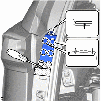
.png) | Protective Tape |
(b) Using a screwdriver, detach the 7 claws and remove the rear combination light cover LH.
HINT:
Tape the screwdriver tip before use.
15. REMOVE REAR COMBINATION LIGHT ASSEMBLY LH
(a) Apply protective tape around the rear combination light assembly LH.
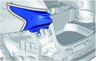
| | Protective Tape |
| (b) Place your hand between the deck trim side panel assembly LH and the body to disconnect the connector. |
|
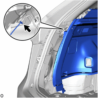
| (c) Disconnect the grommet and pull out the wire harness. |
|

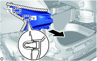
(d) Remove the 3 screws.
| (e) Pull the rear combination light assembly LH towards the rear of the vehicle to detach the pin and guide and remove it. NOTICE: Pull the rear combination light assembly LH straight towards the rear of the vehicle to prevent the guide from becoming damaged. |
|
READ NEXT:
 Disassembly
DISASSEMBLY PROCEDURE 1. PRECAUTION NOTICE:
Be sure to read Precaution thoroughly before servicing.
Click here
Handle components indoors as much as possible to prevent foreign matter from enter
Inspection
INSPECTION PROCEDURE 1. INSPECT REAR COMBINATION LIGHT ASSEMBLY LH (a) Apply battery voltage to the connector and check the light illumination condition. OK: Battery Connection Specified Cond
Reassembly
REASSEMBLY CAUTION / NOTICE / HINT HINT:
Use the same procedure for the RH and LH sides.
The procedure listed below is for the LH side.
PROCEDURE 1. INSTALL REAR COMBINATION LIGHT SOCKET AND W
SEE MORE:
Inverter Coolant Pump Speed Signal (P314A-828)
DESCRIPTION Refer to the description for DTC P0C73-776. Click here The inverter water pump assembly sends the inverter water pump speed (measured value) signal to the hybrid vehicle control ECU. If the inverter water pump speed (measured value) signal is not sent to the hybrid vehicle control ECU
Generator Position Sensor Circuit Range / Performance (P0A4C-518,P0A4C-811)
DTC SUMMARY MALFUNCTION DESCRIPTION These DTCs indicate that a large current flowed in the inverter for the generator. The cause of this malfunction may be one of the following: Area Main Malfunction Description Step Inverter low-voltage circuit The connectors are not connected properly
