Lexus NX: Installation
Lexus NX Service Manual / Vehicle Interior / Meter / Gauge / Display / Headup Display Switch / Installation
INSTALLATION
PROCEDURE
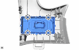
1. INSTALL HEADUP DISPLAY SWITCH ASSEMBLY
| (a) Attach the 4 claws to install the headup display switch assembly. |
|
2. INSTALL NO. 1 SWITCH HOLE BASE
Click here .gif)
3. INSTALL LOWER NO. 1 INSTRUMENT PANEL FINISH PANEL
Click here
4. INSTALL NO. 1 INSTRUMENT PANEL UNDER COVER SUB-ASSEMBLY
Click here
5. INSTALL NO. 1 INSTRUMENT PANEL SAFETY PAD SUB-ASSEMBLY
Click here
6. INSTALL INSTRUMENT SIDE PANEL LH
Click here
7. INSTALL UPPER NO. 2 CONSOLE PANEL GARNISH
Click here
8. INSTALL CONSOLE ARMREST ASSEMBLY
Click here
READ NEXT:
 Parts Location
PARTS LOCATION ILLUSTRATION *1 HEADUP DISPLAY SWITCH ASSEMBLY *2 METER MIRROR SUB-ASSEMBLY *3 FORWARD RECOGNITION CAMERA *4 NO. 2 ENGINE ROOM RELAY BLOCK - ECU-B NO.1 FUSE *5
System Diagram
SYSTEM DIAGRAM
SEE MORE:
Data List / Active Test
DATA LIST / ACTIVE TEST DATA LIST HINT: Using the Techstream to read the Data List allows the values or states of switches, sensors, actuators and other items to be read without removing any parts. This non-intrusive inspection can be very useful because intermittent conditions or signals may be dis
Terminals Of Ecu
TERMINALS OF ECU CHECK INSTRUMENT PANEL JUNCTION BLOCK ASSEMBLY AND MAIN BODY ECU (MULTIPLEX NETWORK BODY ECU) *1 Main Body ECU (Multiplex Network Body ECU) - - (a) Remove the main body ECU (multiplex network body ECU) from the instrument panel junction block assembly. Click here (b)
© 2016-2024 Copyright www.lexunx.com
