Lexus NX: Installation
INSTALLATION
PROCEDURE
1. INSTALL NO. 3 MOTOR WATER JACKET COVER ASSEMBLY
(a) Remove any remaining seal packing from the transaxle housing installation surface and bolt holes.
NOTICE:
- Clean and degrease the installation surface and bolt holes.
- Do not allow any remaining seal packing to enter the coolant path when cleaning.
| (b) Apply seal packing in a continuous line as shown in the illustration. Seal Packing: Toyota Genuine Seal Packing 1282B, Three Bond 1282B or equivalent Standard Seal Diameter: 1.5 mm (0.0591 in.) or more. NOTICE: Remove any oil from the contact surface. |
|
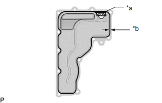
(c) Install a new No. 3 motor water jacket cover assembly to the hybrid vehicle transaxle with 12 new bolts.
Torque:
10 N·m {102 kgf·cm, 7 ft·lbf}
NOTICE:
- Install the No. 3 motor water jacket cover assembly within 3 minutes and tighten the bolts within 10 minutes after applying seal packing.
- Do not add coolant within 2 hours after installing the No. 3 motor water jacket cover assembly.
- Do not start the engine for at least 2 hours after installing the No. 3 motor water jacket cover assembly.
2. INSTALL NO. 1 MOTOR WATER JACKET COVER ASSEMBLY
(a) Remove any remaining seal packing from the transaxle housing installation surface and bolt holes.
NOTICE:
- Clean and degrease the installation surface and bolt holes.
- Do not allow any remaining seal packing to enter the coolant path when cleaning.
| (b) Apply seal packing in a continuous line as shown in the illustration. Seal Packing: Toyota Genuine Seal Packing 1282B, Three Bond 1282B or equivalent Standard Seal Diameter: 1.5 mm (0.0591 in.) or more. NOTICE: Remove any oil from the contact surface. |
|
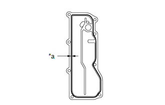
(c) Install a new No. 1 motor water jacket cover assembly to the hybrid vehicle transaxle with 8 new bolts.
Torque:
10 N·m {102 kgf·cm, 7 ft·lbf}
NOTICE:
- Install the No. 1 motor water jacket cover assembly within 3 minutes and tighten the bolts within 10 minutes after applying seal packing.
- Do not add coolant within 2 hours after installing the No. 1 motor water jacket cover assembly.
- Do not start the engine for at least 2 hours after installing the No. 1 motor water jacket cover assembly.
3. INSTALL NO. 2 AUTOMATIC TRANSMISSION CASE COVER
Click here .gif)
4. INSTALL OIL COOLER TUBE CLAMP
Click here
5. INSTALL NO. 1 TRANSMISSION CONTROL CABLE BRACKET
Click here
6. INSTALL FRONT ENGINE MOUNTING BRACKET
Click here
7. INSTALL HYBRID VEHICLE TRANSAXLE ASSEMBLY
Click here
8. INSTALL NO. 2 MOTOR WATER JACKET COVER ASSEMBLY
(a) Remove any remaining seal packing from the transaxle housing installation surface and bolt holes.
NOTICE:
- Clean and degrease the installation surface and bolt holes.
- Do not allow any remaining seal packing to enter the coolant path when cleaning.
| (b) Apply seal packing in a continuous line as shown in the illustration. Seal Packing: Toyota Genuine Seal Packing 1282B, Three Bond 1282B or equivalent Standard Seal Diameter: 1.5 mm (0.0591 in.) or more. NOTICE: Remove any oil from the contact surface. |
|
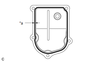
(c) Install a new No. 2 motor water jacket cover assembly to the hybrid vehicle transaxle with 5 new bolts.
Torque:
10 N·m {102 kgf·cm, 7 ft·lbf}
NOTICE:
- Install the No. 2 motor water jacket cover assembly within 3 minutes and tighten the bolts within 10 minutes after applying seal packing.
- Do not add coolant within 2 hours after installing the No. 2 motor water jacket cover assembly.
- Do not start the engine for at least 2 hours after installing the No. 2 motor water jacket cover assembly.
9. ADD COOLANT (for Inverter Coolant)
Click here
10. INSPECT FOR COOLANT LEAK (for Inverter Coolant)
Click here
11. INSTALL NO. 1 ENGINE UNDER COVER ASSEMBLY
Click here
READ NEXT:
 Components
COMPONENTS ILLUSTRATION *1 NO. 1 ENGINE UNDER COVER ASSEMBLY - - ILLUSTRATION *1 INVERTER BRACKET ASSEMBLY *2 INVERTER WATER PUMP WITH MOTOR ASSEMBLY *3 NO. 5 INVERTER COO
Removal
REMOVAL PROCEDURE 1. REMOVE NO. 1 ENGINE UNDER COVER ASSEMBLY Click here 2. REMOVE INVERTER WITH CONVERTER ASSEMBLY Click here 3. REMOVE INVERTER WATER PUMP WITH MOTOR ASSEMBLY Click here 4
SEE MORE:
Initialization
INITIALIZATION DESCRIPTION (a) Perform initialization and calibration of the linear solenoid valve when the brake booster with master cylinder assembly, brake pedal stroke sensor assembly or brake pedal is replaced. Follow the procedure to perform initialization. HINT:
If there is a problem with
Removal
REMOVAL CAUTION / NOTICE / HINT HINT:
Use the same procedure for the RH and LH sides.
The procedure listed below is for the LH side.
PROCEDURE 1. REMOVE FRONT DOOR TRIM COVER LH Click here 2. REMOVE FRONT DOOR INSIDE HANDLE BEZEL PLUG LH Click here 3. REMOVE POWER WINDOW REGULATOR MAST
