Lexus NX: Knock Sensor
Components
COMPONENTS
ILLUSTRATION
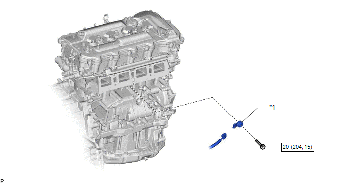
| *1 | KNOCK CONTROL SENSOR | - | - |
.png) | N*m (kgf*cm, ft.*lbf) : Specified torque | - | - |
Removal
REMOVAL
PROCEDURE
1. REMOVE INTAKE MANIFOLD
Click here .gif)
2. REMOVE KNOCK CONTROL SENSOR
| (a) Disconnect the knock control sensor connector. |
|
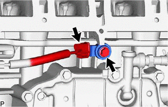
(b) Remove the bolt and knock control sensor.
Inspection
INSPECTION
PROCEDURE
1. INSPECT KNOCK CONTROL SENSOR
(a) Measure the resistance according to the value(s) in the table below.
Standard Resistance:
| Tester Connection | Condition | Specified Condition |
|---|---|---|
| 1 - 2 | 20°C (68°F) | 120 to 280 kΩ |
If the result is not as specified, replace the knock control sensor.
Installation
INSTALLATION
CAUTION / NOTICE / HINT
HINT:
Perform "Inspection After Repairs" after replacing the knock control sensor.
Click here .gif)
PROCEDURE
1. INSTALL KNOCK CONTROL SENSOR
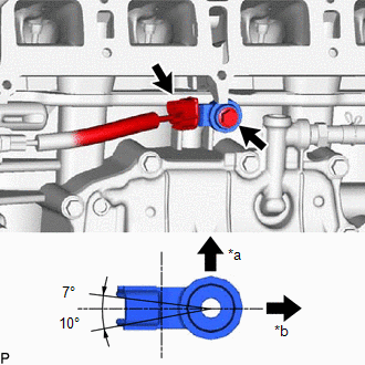
| (a) Install the knock control sensor with the bolt so that the knock control sensor is angled as shown in the illustration. Torque: 20 N·m {204 kgf·cm, 15 ft·lbf} NOTICE:
HINT: Perform "Inspection After Repairs" after replacing the knock control sensor. Click here |
|
(b) Connect the knock control sensor connector.
2. INSTALL INTAKE MANIFOLD
Click here
READ NEXT:
 Manifold Absolute Pressure Sensor
ComponentsCOMPONENTS ILLUSTRATION *1 MANIFOLD ABSOLUTE PRESSURE SENSOR *2 VACUUM HOSE N*m (kgf*cm, ft.*lbf): Specified torque - - On-vehicle InspectionON-VEHICLE INSPECTION P
Mass Air Flow Meter
ComponentsCOMPONENTS ILLUSTRATION *1 MASS AIR FLOW METER SUB-ASSEMBLY - - On-vehicle InspectionON-VEHICLE INSPECTION CAUTION / NOTICE / HINT NOTICE:
Perform the mass air flow meter s
Relay
On-vehicle InspectionON-VEHICLE INSPECTION PROCEDURE 1. INSPECT JUNCTION BLOCK *1 Main Body ECU - - *a Component without harness connected (Junction Block) *b Component without ma
SEE MORE:
Installation
INSTALLATION PROCEDURE 1. INSTALL STOP LIGHT SWITCH ASSEMBLY (a) Turn the stop light switch assembly in the clockwise direction until it reaches the standard shaft protrusion amount and temporarily install it. Standard: 0.5 to 1.7 mm (0.0197 to 0.0669 in.) NOTICE: Do not depress the brake pedal.
Initialization
INITIALIZATION INITIALIZE SLIDING ROOF SYSTEM NOTICE:
When the roof glass is adjusted or removed/installed, or the sliding roof drive gear sub-assembly is replaced, the glass position cannot be determined and the sliding roof drive gear sub-assembly must be initialized (pulse sensor initial posit
