Lexus NX: Relay
On-vehicle Inspection
ON-VEHICLE INSPECTION
PROCEDURE
1. INSPECT JUNCTION BLOCK
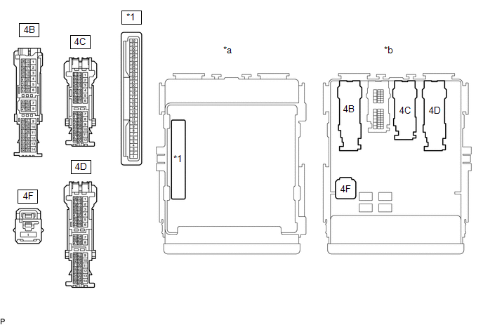
| *1 | Main Body ECU | - | - |
| *a | Component without harness connected (Junction Block) | *b | Component without main body ECU connected (Junction Block) |
NOTICE:
Before performing the relay inspections for the relays of the junction block, inspect the ECU-IG NO. 2, ECU-IG NO. 4 and ECU-IG NO. 5 fuses.
(a) Inspect the IG1 NO. 1 relay.
(1) Measure the resistance according to the value(s) in the table below.
Standard Resistance:
| Tester Connection | Condition | Specified Condition |
|---|---|---|
| 4F-1 - 4C-21 | Battery voltage not applied to terminals 4B-46 and -4D-28 | 10 kΩ or higher |
| Battery voltage applied to terminals 4B-46 and 4D-28 | Below 1 Ω |
If the result is not as specified, replace the junction block.
(b) Inspect the IG1 NO. 2 relay.
(1) Measure the resistance according to the value(s) in the table below.
Standard Resistance:
| Tester Connection | Condition | Specified Condition |
|---|---|---|
| 4F-1 - 4C-41 | Battery voltage not applied to terminals 4B-46 and -4D-28 | 10 kΩ or higher |
| Battery voltage applied to terminals 4B-46 and 4D-28 | Below 1 Ω |
If the result is not as specified, replace the junction block.
(c) Inspect the IG1 NO. 3 relay.
(1) Measure the resistance according to the value(s) in the table below.
Standard Resistance:
| Tester Connection | Condition | Specified Condition |
|---|---|---|
| 4F-1 - 4D-34 | Battery voltage not applied to terminals 4B-46 and -4D-28 | 10 kΩ or higher |
| Battery voltage applied to terminals 4B-46 and 4D-28 | Below 1 Ω |
If the result is not as specified, replace the junction block.
2. INSPECT EFI MAIN RELAY (EFI MAIN)
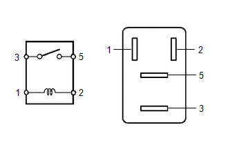
(a) Measure the resistance according to the value(s) in the table below.
Standard Resistance:
| Tester Connection | Condition | Specified Condition |
|---|---|---|
| 3 - 5 | Battery voltage not applied to terminals 1 and 2 | 10 kΩ or higher |
| Battery voltage applied to terminals 1 and 2 | Below 1 Ω |
If the result is not as specified, replace the EFI main relay.
3. INSPECT EFI MAIN NO. 2 RELAY (EFI MAIN NO. 2)
(a) Measure the resistance according to the value(s) in the table below.
Standard Resistance:
| Tester Connection | Condition | Specified Condition |
|---|---|---|
| 3 - 5 | Battery voltage not applied to terminals 1 and 2 | 10 kΩ or higher |
| Battery voltage applied to terminals 1 and 2 | Below 1 Ω |
If the result is not as specified, replace the EFI main No. 2 relay.
4. INSPECT IGNITION NO. 2 MAIN RELAY (IG2-MAIN)
(a) Measure the resistance according to the value(s) in the table below.
Standard Resistance:
| Tester Connection | Condition | Specified Condition |
|---|---|---|
| 3 - 5 | Battery voltage not applied to terminals 1 and 2 | 10 kΩ or higher |
| Battery voltage applied to terminals 1 and 2 | Below 1 Ω |
If the result is not as specified, replace the ignition No. 2 main relay.
READ NEXT:
 Precaution
PRECAUTION INITIALIZATION NOTICE: Perform Registration (VIN registration) when replacing the ECM. Click here DISCONNECT CABLE FROM NEGATIVE AUXILIARY BATTERY TERMINAL NOTICE:
After the power swit
Definition Of Terms
DEFINITION OF TERMS Term Definition Monitor Description Description of what the ECM monitors and how it detects malfunctions (monitoring purpose and details). Related DTCs Group of di
SEE MORE:
How To Proceed With Troubleshooting
CAUTION / NOTICE / HINT HINT:
Use the following procedure to troubleshoot the safety connect system.
*: Use the Techstream.
PROCEDURE 1. VEHICLE BROUGHT TO WORKSHOP
NEXT 2. CUSTOMER PROBLEM ANALYSIS CHECK AND SYMPTOM CHECK HINT:
In troubleshooting, confi
ACC Signal Circuit
DESCRIPTION This circuit detects whether the power switch is on (ACC) or off, and sends this information to the main body ECU (multiplex network body ECU). WIRING DIAGRAM CAUTION / NOTICE / HINT NOTICE:
Inspect the fuses for circuits related to this system before performing the following procedu
