- Inverter Coolant Water Temperature
- Ambient Temperature
- (Inverter) W/P Run Control Duty
- Inverter W/P Revolution
Lexus NX: Motor Electronics Coolant Temperature Sensor Circuit Range / Performance (P0A01-726,P0A04-725)
Lexus NX Service Manual / Engine & Hybrid System / 2ar-fxe (hybrid / Battery Control) / Hybrid Control System / Motor Electronics Coolant Temperature Sensor Circuit Range / Performance (P0A01-726,P0A04-725)
DTC SUMMARY
MALFUNCTION DESCRIPTION
These DTCs indicate the temperature sensor value is abnormal. The cause of this malfunction may be one of the following:
| Area | Main Malfunction Description | Step |
|---|---|---|
| Inverter low-voltage circuit | The connectors are not connected properly | 2 |
| Hybrid cooling system | Coolant circulation abnormal (frozen or leaking, etc.) | 3 |
| Inside of inverter | Inverter with converter assembly internal circuit malfunction | 3 |
DESCRIPTION
The hybrid vehicle control ECU detects HV coolant temperature using the coolant temperature sensor built into the inverter with converter assembly. The hybrid vehicle control ECU uses signals from the coolant temperature sensor to check the effectiveness of the inverter cooling system. If necessary, the hybrid vehicle control ECU will limit inverter output to help prevent inverter overheating. The hybrid vehicle control ECU also detects malfunctions in the sensor based on the HV coolant temperature sensor values. The inverter with converter assembly detects malfunctions in the HV coolant temperature sensor and its wiring.
| DTC No. | Detection Item | DTC Detection Condition | Trouble Area | MIL | Warning Indicate |
|---|---|---|---|---|---|
| P0A01-726 | Motor Electronics Coolant Temperature Sensor Circuit Range / Performance | Abnormal deviation in inverter coolant temperature sensor output. Both of the following conditions are met for 10 seconds or more:
(1 trip detection logic) |
| Comes on | Master Warning Light: Comes on |
| P0A04-725 | Motor Electronics Coolant Temperature Sensor Circuit Intermittent | Sudden change in HV coolant temperature sensor output or hunting: Unusual sudden change in HV coolant temperature sensor output occurs and the offset continues for a certain period of time. Unusual sudden change in HV coolant temperature sensor output occurs repeatedly. (1 trip detection logic) |
| Comes on | Master Warning Light: Comes on |
| DTC No. | ECU Data List |
|---|---|
| P0A01-726 | |
| P0A04-725 |
MONITOR DESCRIPTION
If the hybrid vehicle control ECU detects a malfunction of the HV coolant temperature sensor, it will illuminate the MIL and store a DTC.
MONITOR STRATEGY
| Related DTCs | P0A01 (INF 726): Motor Electronics Coolant Temperature Sensor Circuit Range / Performance P0A04 (INF 725): Motor Electronics Coolant Temperature Sensor Circuit Intermittent |
| Required sensors/components | HV coolant temperature sensor |
| Frequency of operation | Continuous |
| Duration | TMC's intellectual property |
| MIL operation | 1 driving cycle |
| Sequence of operation | None |
TYPICAL ENABLING CONDITIONS
| The monitor will run whenever the following DTCs are not stored | TMC's intellectual property |
| Other conditions belong to TMC's intellectual property | - |
TYPICAL MALFUNCTION THRESHOLDS
| TMC's intellectual property | - |
COMPONENT OPERATING RANGE
| Hybrid vehicle control ECU | DTC P0A01 (INF 726) is not detected DTC P0A04 (INF 725) is not detected |
CONFIRMATION DRIVING PATTERN
- Connect the Techstream to the DLC3.
- Turn the power switch on (IG) and turn the Techstream on.
- Clear the DTCs (even if no DTCs are stored, perform the clear DTC procedure).
- Turn the power switch off and wait for 30 seconds or more.
- Turn the power switch on (IG) and turn the Techstream on.
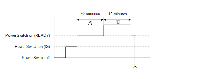
- Turn the power switch on (READY).
-
With the shift lever in P, wait for 90 seconds. [A]
HINT:
Check that there are no abnormalities (abnormal sounds, coolant leaks, DTC output, etc).
- Perform a road test according to the freeze frame data "Vehicle Spd" for approximately 10 minutes. [B]
- Enter the following menus: Powertrain / Hybrid Control / Trouble Codes. [C]
-
Read the current DTCs.
HINT:
- If a current DTC is output, the system is malfunctioning.
- If a current DTC is not output and want to confirm permanent DTC, perform the following procedure.
- Check that permanent DTCs are cleared. If no permanent DTC is output, the system is normal.
- If the permanent DTCs are not cleared, perform a universal trip, and then check for permanent DTCs again.
CAUTION / NOTICE / HINT
CAUTION:
- Before inspecting the high-voltage system or disconnecting the low voltage connector of the inverter with converter assembly, take safety precautions such as wearing insulated gloves and removing the service plug grip to prevent electrical shocks. After removing the service plug grip, put it in your pocket to prevent other technicians from accidentally reconnecting it while you are working on the high-voltage system.
-
After removing the service plug grip, wait for at least 10 minutes before touching any of the high-voltage connectors or terminals. After waiting for 10 minutes, check the voltage at the terminals in the inspection point in the inverter with converter assembly. The voltage should be 0 V before beginning work.
Click here
.gif)
HINT:
Waiting for at least 10 minutes is required to discharge the high-voltage capacitor inside the inverter with converter assembly.
NOTICE:
After turning the power switch off, waiting time may be required before disconnecting the cable from the negative (-) auxiliary battery terminal. Therefore, make sure to read the disconnecting the cable from the negative (-) auxiliary battery terminal notices before proceeding with work.
Click here
HINT:
After the repair, clear the DTCs and perform the following procedure to check that DTCs are not output.
- Turn the power switch on (READY) and wait for 90 seconds or more.
- Drive the vehicle for approximately 10 minutes referring to the following freeze frame data or Data List items: "Vehicle Spd".
PROCEDURE
| 1. | CHECK DTC OUTPUT (HYBRID CONTROL) |
(a) Connect the Techstream to the DLC3.
(b) Turn the power switch on (IG).
(c) Enter the following menus: Powertrain / Hybrid Control / Trouble Codes.
(d) Check for DTCs.
Powertrain > Hybrid Control > Trouble Codes| Result | Proceed to |
|---|---|
| P0A01-726 or P0A04-725 only is output, or DTCs except the ones in the table below are also output. | A |
| Any of the following DTCs are also output. | B |
| Relevant DTC | |
|---|---|
| P0A93-346 | Inverter Cooling System Performance |
| P0C73-776 | Motor Electronics Coolant Pump "A" Control Performance |
| P314A-828 | Inverter Coolant Pump Speed Signal |
HINT:
P0A01-726 or P0A04-725 may be output as a result of the malfunction indicated by the DTCs above.
(e) Turn the power switch off.
| B | .gif) | GO TO DTC CHART (HYBRID CONTROL SYSTEM) |
|
.gif)
| 2. | CHECK CONNECTOR CONNECTION CONDITION (INVERTER WITH CONVERTER ASSEMBLY CONNECTOR) |
Click here
| Result | Proceed to |
|---|---|
| OK | A |
| NG (The connector is not connected securely.) | B |
| NG (The terminals are not making secure contact or are deformed, or water or foreign matter exists in the connector.) | C |
| B | | CONNECT SECURELY |
| C | | REPAIR OR REPLACE HARNESS OR CONNECTOR |
|
| 3. | CHECK COOLING SYSTEM |
Click here
HINT:
If the "Cooling System" inspection results are normal, perform the next step.
| NEXT | | REPLACE INVERTER WITH CONVERTER ASSEMBLY |
READ NEXT:
 Motor Electronics Coolant Temperature Sensor Circuit Low (P0A02-719,P0A03-720)
DESCRIPTION Refer to the description for DTC P0A01-726. Click here DTC No. Detection Item DTC Detection Condition Trouble Area MIL Warning Indicate P0A02-719 Motor Electronics Coo
DC / DC Converter Status Circuit (P0A08-264)
DESCRIPTION The DC/DC converter converts the DC 244.8 V of the HV battery into DC 12 V in order to supply power to areas such as the vehicle's lighting, audio, and ECU systems. In addition, it charges
DC / DC Converter Status Circuit Low Input (P0A09-265)
DESCRIPTION Refer to the description for DTC P0A08-264. Click here The hybrid vehicle control ECU sends a signal to the DC/DC converter to prohibit its control and receives signals indicating a nor
SEE MORE:
Installation
INSTALLATION CAUTION / NOTICE / HINT CAUTION: Wear protective gloves. Sharp areas on the parts may injure your hands. PROCEDURE 1. INSTALL SEPARATE TYPE REAR SEATBACK COVER LH (REAR SEATBACK HEATER ASSEMBLY LH) (for LH Side) HINT:
When installing the seat cover, refer to the precautions in order
Inspection
INSPECTION PROCEDURE 1. INSPECT TIRES (a) Check the tires for wear and proper inflation pressure. Specified Pressure (When Tire is Cool): Tire Size Front kPa (kgf/cm2, psi) Rear kPa (kgf/cm2, psi) 225/65R17 102H 240 (2.4, 35)*1 250 (2.5, 36)*2 240 (2.4, 35)*1 250 (2.5, 36)*2 225/
© 2016-2024 Copyright www.lexunx.com
