Lexus NX: Mute Signal Circuit between Radio Receiver and Stereo Component Amplifier
DESCRIPTION
This circuit sends a signal to the stereo component amplifier assembly to mute noise. Because of that, the noise produced by changing the sound source ceases.
If there is an open in the circuit, noise can be heard from the speakers when changing the sound source.
If there is a short in the circuit, even though the stereo component amplifier assembly is functioning normally, no sound or only an extremely faint sound can be heard.
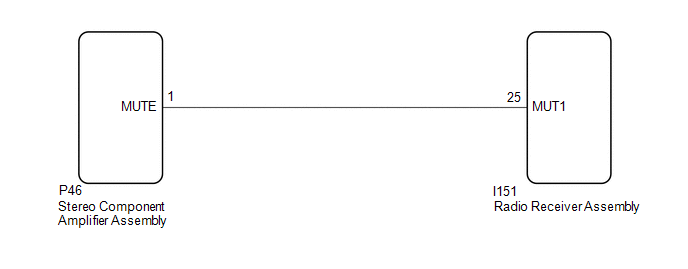
WIRING DIAGRAM
CAUTION / NOTICE / HINT
NOTICE:
When replacing the radio receiver assembly, always replace it with a new one.
If a radio receiver assembly which was installed to another vehicle is used, the following may occur:
- A communication malfunction DTC may be stored.
- The radio receiver assembly may not operate normally.
HINT:
Depending on the parts that are replaced during vehicle inspection or maintenance, performing initialization, registration or calibration may be needed. Refer to Precaution for Audio and Visual System.
Click here .gif)
PROCEDURE
| 1. | CHECK STEREO COMPONENT AMPLIFIER ASSEMBLY |
| (a) Remove the stereo comonent amplifier assembly with the connector(s) still connected. Click here |
|
(b) Measure the voltage according to the value(s) in the table below.
Standard Voltage:
| Tester Connection | Condition | Specified Condition |
|---|---|---|
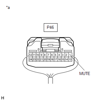
| P46-1 (MUTE) - Body ground | Power switch on (ACC), audio system playing → Changing modes | 2.0 V or higher → Below 1 V |
| OK | .gif) | PROCEED TO NEXT SUSPECTED AREA SHOWN IN PROBLEM SYMPTOMS TABLE |
|
.gif)
| 2. | CHECK HARNESS AND CONNECTOR (RADIO RECEIVER ASSEMBLY - STEREO COMPONENT AMPLIFIER ASSEMBLY) |
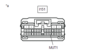
(a) Disconnect the I151 radio receiver assembly connector.
(b) Disconnect the P46 stereo component amplifier assembly connector.
(c) Measure the resistance according to the value(s) in the table below.
Standard Resistance:
| Tester Connection | Condition | Specified Condition |
|---|---|---|
| I151-25 (MUT1) - P46-1 (MUTE) | Always | Below 1 Ω |
| I151-25 (MUT1) - Body ground | Always | 10 kΩ or higher |
| NG | | REPAIR OR REPLACE HARNESS OR CONNECTOR |
|
| 3. | CHECK STEREO COMPONENT AMPLIFIER ASSEMBLY (OUTPUT SIGNAL) |
| (a) Disconnect the radio receiver assembly connector. |
|
(b) Measure the voltage according to the value(s) in the table below.
Standard Voltage:
| Tester Connection | Condition | Specified Condition |
|---|---|---|
| I151-25 (MUT1) - Body ground | Power switch on (ACC), audio system is playing | 2.0 V or higher |
| OK | | REPLACE RADIO RECEIVER ASSEMBLY |
| NG | | REPLACE STEREO COMPONENT AMPLIFIER ASSEMBLY |
READ NEXT:
 Mute Signal Circuit between Stereo Component Amplifier and Telematics Transceiver
DESCRIPTION This DCM (telematics transceiver) sends a mute signal to the stereo component amplifier assembly. The stereo component amplifier assembly controls the volume according to the mute signal f
AVC-LAN Circuit
DESCRIPTION Each audio system component connected to the AVC-LAN (communication bus) transfers switch signals using the audio visual communication local area network. If a short to +B or short to grou
Vehicle Speed Signal Circuit between Stereo Component Amplifier and Combination Meter
DESCRIPTION The stereo component amplifier assembly receives a vehicle speed signal from the combination meter assembly to control the ASL function. HINT:
A voltage of 12 V or 5 V is output from ea
SEE MORE:
Installation
INSTALLATION PROCEDURE 1. INSTALL BLIND SPOT MONITOR BUZZER (a) Attach the clamp to install the blind spot monitor buzzer. (b) Connect the connector. 2. INSTALL DECK TRIM SIDE PANEL ASSEMBLY RH Click here 3. INSTALL NO. 1 LUGGAGE COMPARTMENT TRIM HOOK Click here 4. INSTALL LUGGAGE HOLD BELT ST
System Description
SYSTEM DESCRIPTION POWER BACK DOOR SYSTEM DESCRIPTION (a) The power back door system controls the power back door by automatically opening and closing the power back door with a motor. (1) The power back door system operates only when the necessary conditions are met. (2) The multiplex network door
