Lexus NX: Navigation Ecu
Lexus NX Service Manual / Audio & Visual & Telematics / Navigation / Multi Info Display / Navigation Ecu
Components
COMPONENTS
ILLUSTRATION
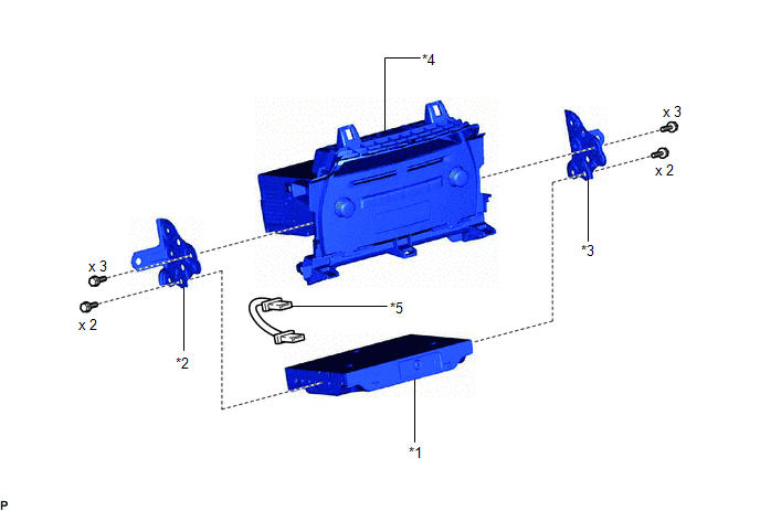
| *1 | NAVIGATION ECU | *2 | NO. 1 RADIO BRACKET |
| *3 | NO. 2 RADIO BRACKET | *4 | RADIO RECEIVER ASSEMBLY WITH BRACKET |
| *5 | NAVIGATION WIRE | - | - |
Removal
REMOVAL
PROCEDURE
1. REMOVE RADIO RECEIVER ASSEMBLY WITH BRACKET
Click here .gif)
2. REMOVE NO. 1 RADIO BRACKET
Click here
3. REMOVE NO. 2 RADIO BRACKET
Click here
4. REMOVE NAVIGATION ECU
| (a) Disconnect the connectors and remove the navigation wire. |
|
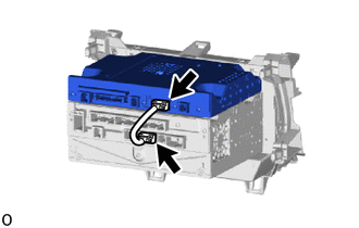
(b) Remove the navigation ECU.
Installation
INSTALLATION
PROCEDURE
1. INSTALL NAVIGATION ECU
| (a) Connect the connectors and install a navigation ECU in the mounting location. |
|
.png)
2. INSTALL NO. 1 RADIO BRACKET
Click here .gif)
3. INSTALL NO. 2 RADIO BRACKET
Click here
4. INSTALL RADIO RECEIVER ASSEMBLY WITH BRACKET
Click here
READ NEXT:
 Precaution
PRECAUTION PRECAUTION FOR DISCONNECTING CABLE FROM NEGATIVE AUXILIARY BATTERY TERMINAL NOTICE: After the power switch is turned off, the radio receiver assembly records various types of memory and set
Parts Location
PARTS LOCATION ILLUSTRATION *A w/ Parking Assist Monitor System *B w/ Panoramic View Monitor System *1 NO. 2 ENGINE ROOM RELAY BLOCK - DCM FUSE (w/ Manual [SOS] Switch) - ECU-B NO.1 FU
SEE MORE:
Removal
REMOVAL PROCEDURE 1. PRECAUTION CAUTION: The hybrid system has high-voltage circuits. Accidents, such as electric shock, or electric leaks may result if the hybrid system is not operated in a correct manner. Make sure to follow the correct procedure. Click here NOTICE: After turning the power swit
Inspection
INSPECTION PROCEDURE 1. INSPECT OUTER MIRROR SWITCH ASSEMBLY (w/ Memory) (a) Check the mirror retract switch. (1) Measure the resistance according to the value(s) in the table below. Standard Resistance: Tester Connection Condition Specified Condition 8 (MR) - 10 (E) Driving positio
© 2016-2024 Copyright www.lexunx.com
