Lexus NX: On-vehicle Inspection
ON-VEHICLE INSPECTION
PROCEDURE
1. INSPECT STOP LIGHT CONTROL ECU ASSEMBLY
| (a) Disconnect the stop light control ECU assembly connector. |
|
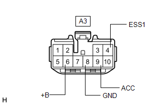
(b) Measure the voltage and resistance on the wire harness side connector according to the value (s) in the table below.
Standard Voltage:
| Tester Connection | Condition | Specified Condition |
|---|---|---|
| A3-4 (ESS1) - A3-8 (GND) | Power switch on (IG) | 11 to 14 V |
| A3-6 (+B) - A3-8 (GND) | Power switch off | 11 to 14 V |
| A3-9 (ACC) - A3-8 (GND) | Power switch on (IG) | 11 to 14 V |
Standard Resistance:
| Tester Connection | Condition | Specified Condition |
|---|---|---|
| A3-8 (GND) - Body ground | Always | Below 1 Ω |
If the result is not as specified, repair or replace the wire harness or connector.
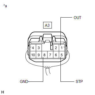
(c) Reconnect the stop light control ECU assembly connector.
| (d) Measure the voltage according to the value (s) in the table below. Standard Voltage:
If the result is not as specified, replace the stop light control ECU assembly. |
|
READ NEXT:
 Removal
REMOVAL PROCEDURE 1. REMOVE DOOR SCUFF PLATE ASSEMBLY LH Click here 2. REMOVE COWL SIDE TRIM BOARD LH Click here 3. REMOVE INSTRUMENT SIDE PANEL LH Click here 4. REMOVE NO. 1 INSTRUMENT
Installation
INSTALLATION PROCEDURE 1. INSTALL STOP LIGHT CONTROL ECU ASSEMBLY (a) Attach the clamp to install the stop light control ECU assembly. (b) Connect the connector. 2. INSTALL LOWER NO. 1 INSTRUMENT PANE
SEE MORE:
Customize Parameters
CUSTOMIZE PARAMETERS CUSTOMIZE SLIDING ROOF SYSTEM HINT: The following items can be customized. NOTICE:
When the customer requests a change in a function, first make sure that the function can be customized.
Be sure to make notes of the current settings before customizing.
When troubleshootin
Short to GND in Outer Mirror Indicator(Master) (C1AB2)
DESCRIPTION This DTC is stored when the blind spot monitor sensor LH detects a ground short in the outer rear view mirror indicator LH. DTC No. Detection Item DTC Detection Condition Trouble Area Note C1AB2 Short to GND in Outer Mirror Indicator(Master) Both of the following cond
