Lexus NX: Removal
REMOVAL
PROCEDURE
1. REMOVE DOOR SCUFF PLATE ASSEMBLY LH
Click here .gif)
2. REMOVE COWL SIDE TRIM BOARD LH
Click here
3. REMOVE INSTRUMENT SIDE PANEL LH
Click here
4. REMOVE NO. 1 INSTRUMENT PANEL SAFETY PAD SUB-ASSEMBLY
Click here
5. REMOVE REAR CONSOLE ARMREST ASSEMBLY
Click here
6. REMOVE UPPER NO. 2 CONSOLE PANEL GARNISH
Click here
7. REMOVE NO. 1 INSTRUMENT PANEL UNDER COVER SUB-ASSEMBLY
Click here
8. REMOVE LOWER NO. 1 INSTRUMENT PANEL FINISH PANEL
Click here
9. REMOVE STOP LIGHT CONTROL ECU ASSEMBLY
| (a) Disconnect the connector. |
|
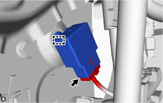
(b) Detach the clamp and remove the stop light control ECU assembly.
READ NEXT:
 Installation
INSTALLATION PROCEDURE 1. INSTALL STOP LIGHT CONTROL ECU ASSEMBLY (a) Attach the clamp to install the stop light control ECU assembly. (b) Connect the connector. 2. INSTALL LOWER NO. 1 INSTRUMENT PANE
Components
COMPONENTS ILLUSTRATION *1 COWL SIDE TRIM BOARD LH *2 DOOR SCUFF PLATE ASSEMBLY LH *3 NO. 1 INSTRUMENT PANEL UNDER COVER SUB-ASSEMBLY *4 STOP LIGHT SWITCH ASSEMBLY *5 STOP LI
SEE MORE:
Buzzer Circuit Short to Battery (C1A4A12)
DESCRIPTION If the forward recognition camera detects a short +B in the buzzer circuit, it will store DTC C1A4A12. DTC No. Detection Item DTC Detection Condition Trouble Area C1A4A12 Buzzer Circuit Short to Battery While the skid control buzzer is sounding, the forward recognition c
ECU Power Source Circuit
DESCRIPTION This circuit is the power source circuit to operate the parking assist ECU. The parking assist ECU controls the panoramic view monitor system. WIRING DIAGRAM CAUTION / NOTICE / HINT NOTICE: Inspect the fuse for circuits related to this system before performing the following procedure.
© 2016-2024 Copyright www.lexunx.com
