Lexus NX: On-vehicle Inspection
ON-VEHICLE INSPECTION
PROCEDURE
1. INSPECT WINDSHIELD WIPER SWITCH ASSEMBLY
(a) w/o Auto Wiper System:
Check the front wiper intermittent operation.
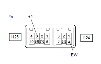
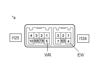
| (1) Connect a voltmeter positive (+) lead to terminal I125-3 (+1) and a negative (-) lead to terminal I124-4 (EW). |
|
(2) Turn the power switch on (IG).
(3) Turn the wiper switch to the INT position.
(4) Operate the intermittent wiper and check the voltage between terminals I125-3 (+1) and I124-4 (EW).
OK:
Voltage changes as shown in the illustration.
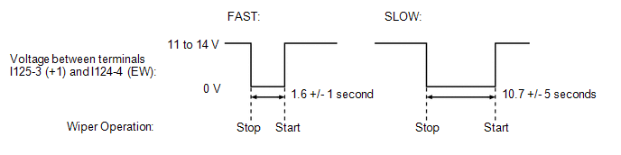
If the result is not as specified, replace the windshield wiper switch assembly.
(b) Check the front washer operation.
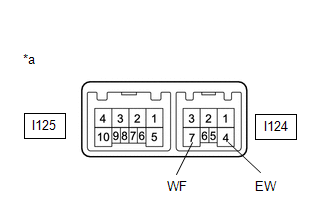
| (1) Connect a voltmeter positive (+) lead to terminal I124-7 (WF) and a negative (-) lead to terminal I124-4 (EW). |
|
(2) Turn the power switch on (IG).
(3) Turn the washer switch on and off, and check the voltage between terminals I124-7 (WF) and I124-4 (EW).
OK:
Voltage changes as shown in the following illustration.
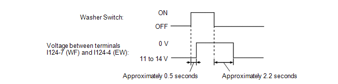
If the result is not as specified, replace the windshield wiper switch assembly.
(c) Check the rear washer operation.
| (1) Connect a voltmeter positive (+) lead to terminal I125-5 (WR) and a negative (-) lead to terminal I124-4 (EW). |
|
(2) Turn the power switch on (IG).
(3) Turn the washer switch on and off, and check the voltage between terminals I125-5 (WR) and I124-4 (EW).
OK:
Voltage changes as shown in the following illustration.
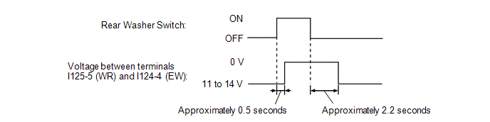
If the result is not as specified, replace the windshield wiper switch assembly.
READ NEXT:
 Removal
REMOVAL PROCEDURE 1. PRECAUTION CAUTION: Be sure to read Precoution thoroughly before serving. Click here NOTICE: After the power switch is turned off, there may be a waiting time before disconnecti
Inspection
INSPECTION PROCEDURE 1. INSPECT WINDSHIELD WIPER SWITCH ASSEMBLY (a) w/o Auto Wiper System: (1) Measure the resistance according to the value(s) in the table below. Standard Resistance: Front Wipe
Installation
INSTALLATION PROCEDURE 1. INSTALL WINDSHIELD WIPER SWITCH ASSEMBLY (a) Attach the claw to install the windshield wiper switch assembly. (b) Connect each connector. 2. INSTALL UPPER STEERING COLUMN COV
SEE MORE:
Checking Monitor Status
CHECKING MONITOR STATUS The purpose of the monitor result (mode 06) is to allow access to the results of on-board diagnostic monitoring tests of specific components/systems that are not continuously monitored. Examples are catalysts and evaporative emissions (EVAP) systems. The monitor result allows
Parts Location
PARTS LOCATION ILLUSTRATION *1 POWER STEERING ECU ASSEMBLY *2 ELECTRIC POWER STEERING COLUMN SUB-ASSEMBLY - POWER STEERING MOTOR ASSEMBLY - MOTOR ROTATION ANGLE SENSOR - TORQUE SENSOR - ECU WIRE SUB-ASSEMBLY *3 SKID CONTROL ECU (BRAKE BOOSTER WITH MASTER CYLINDER ASSEMBLY) *4 NO.
