Lexus NX: Panoramic View Monitor Switch
Inspection
INSPECTION
PROCEDURE
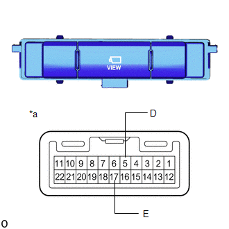
1. INSPECT NO. 2 COMBINATION SWITCH ASSEMBLY (for Type A)
(a) Remove the No. 2 combination switch assembly.
Click here .gif)
| (b) Measure the resistance according to the value(s) in the table below. Standard Resistance:
If the result is not as specified, replace the No. 2 combination switch assembly (panoramic view monitor switch). |
|
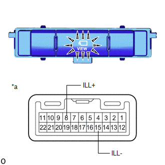
| (c) Check that the switch illuminates. (1) Apply battery voltage to the No. 2 combination switch assembly (panoramic view monitor switch) and check that the switch illuminates. OK:
If the result is not as specified, replace the No. 2 combination switch assembly (panoramic view monitor switch). |
|
(d) Install the No. 2 combination switch assembly.
Click here
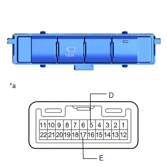
2. INSPECT NO. 2 COMBINATION SWITCH ASSEMBLY (for Type B)
(a) Remove the No. 2 combination switch assembly.
Click here
| (b) Measure the resistance according to the value(s) in the table below. Standard Resistance:
If the result is not as specified, replace the No. 2 combination switch assembly (panoramic view monitor switch). |
|
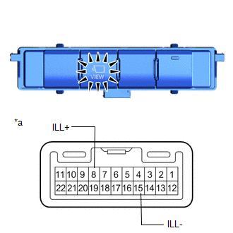
| (c) Check that the switch illuminates. (1) Apply battery voltage to the No. 2 combination switch assembly (panoramic view monitor switch) and check that the switch illuminates. OK:
If the result is not as specified, replace the No. 2 combination switch assembly (panoramic view monitor switch). |
|
(d) Install the No. 2 combination switch assembly.
Click here
READ NEXT:
 Precaution
PRECAUTION POINTS TO NOTE WHEN SERVICING (a) Pay attention to the following points when servicing. (1) When disconnecting the cable from the negative (-) auxiliary battery terminal, "!" mark may appea
Parts Location
PARTS LOCATION ILLUSTRATION *A w/ Blind Spot Monitor System - - *1 FRONT TELEVISION CAMERA ASSEMBLY *2 REAR TELEVISION CAMERA ASSEMBLY *3 SIDE TELEVISION CAMERA ASSEMBLY RH
SEE MORE:
Installation
INSTALLATION CAUTION / NOTICE / HINT HINT:
Use the same procedure for the RH and LH sides.
The procedure listed below is for the LH side.
PROCEDURE 1. INSTALL REAR UPPER COIL SPRING INSULATOR LH *a 10 mm or less (a) Install the rear upper coil spring insulator to the rear coil sprin
Diagnostic Trouble Code Chart
DIAGNOSTIC TROUBLE CODE CHART Front Camera System DTC No. Detection Item Link C10001C Control Module Internal Temperature Sensor "A" Circuit Circuit Voltage Out of Range C10051C Control Module Internal Temperature Sensor "B" Circuit Circuit Voltage Out of Range C100A
