Lexus NX: Parts Location
PARTS LOCATION
ILLUSTRATION
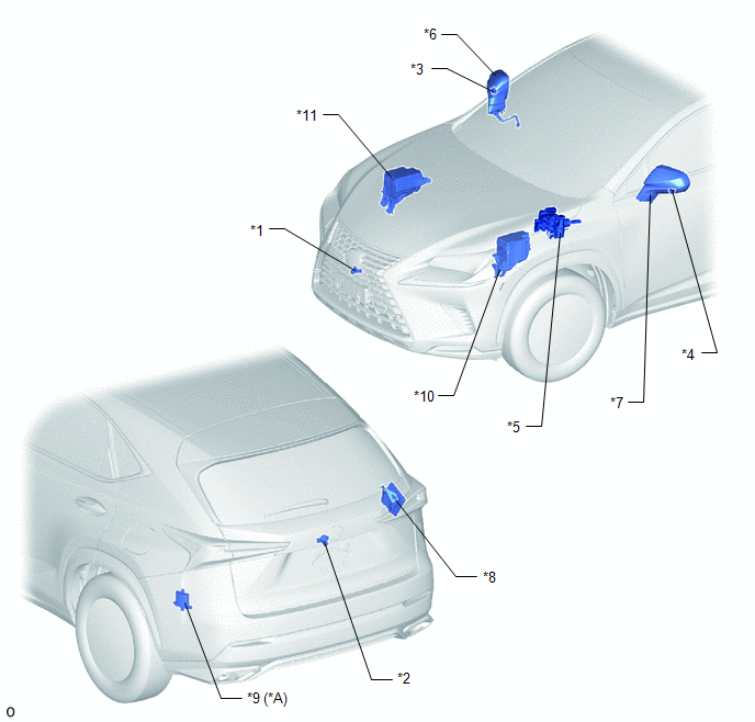
| *A | w/ Blind Spot Monitor System | - | - |
| *1 | FRONT TELEVISION CAMERA ASSEMBLY | *2 | REAR TELEVISION CAMERA ASSEMBLY |
| *3 | SIDE TELEVISION CAMERA ASSEMBLY RH | *4 | SIDE TELEVISION CAMERA ASSEMBLY LH |
| *5 | BRAKE BOOSTER WITH MASTER CYLINDER ASSEMBLY (SKID CONTROL ECU) | *6 | OUTER REAR VIEW MIRROR ASSEMBLY RH - OUTER MIRROR RETRACTOR RH |
| *7 | OUTER REAR VIEW MIRROR ASSEMBLY LH - OUTER MIRROR RETRACTOR LH | *8 | PARKING ASSIST ECU |
| *9 | BLIND SPOT MONITOR SENSOR LH | *10 | ENGINE ROOM RELAY BLOCK - ECU-B NO.4 FUSE |
| *11 | NO. 2 ENGINE ROOM RELAY BLOCK - ECU-IG NO.6 FUSE - ECU-B NO.2 FUSE | - | - |
ILLUSTRATION
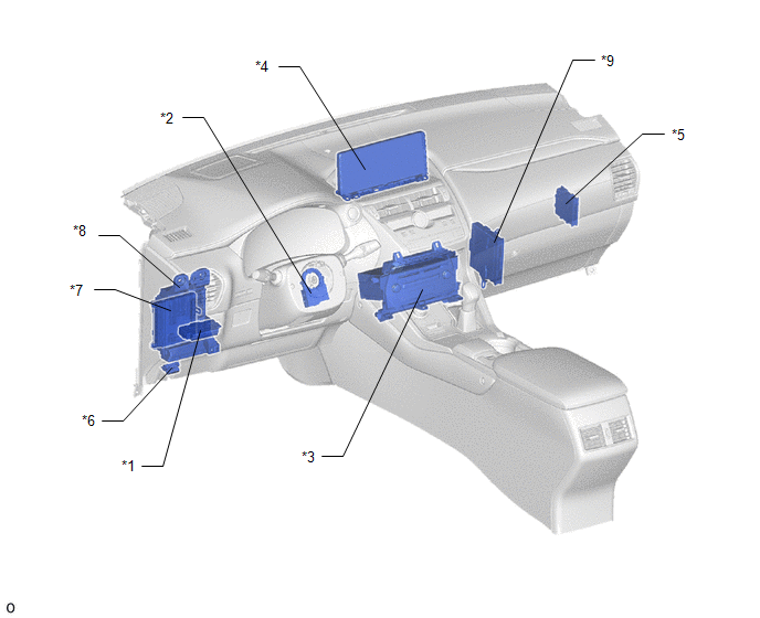
| *1 | NO. 2 COMBINATION SWITCH ASSEMBLY (PANORAMIC VIEW MONITOR MAIN SWITCH) | *2 | STEERING SENSOR |
| *3 | RADIO RECEIVER ASSEMBLY | *4 | MULTI-DISPLAY ASSEMBLY |
| *5 | CLEARANCE WARNING ECU ASSEMBLY | *6 | DLC3 |
| *7 | MAIN BODY ECU (MULTIPLEX NETWORK BODY ECU) | *8 | INSTRUMENT PANEL JUNCTION BLOCK ASSEMBLY - ECU-IG NO.1 FUSE - ACC FUSE |
| *9 | HYBRID VEHICLE CONTROL ECU | - | - |
READ NEXT:
 System Diagram
SYSTEM DIAGRAM Sender Receiver Signal Line
*: w/ Blind Spot Monitor System
Parking Assist ECU Multi-display Assembly Display GVIF cable Radio Receiver Assembly Multi-di
System Description
SYSTEM DESCRIPTION GENERAL (a) This system has front, passenger side, driver side and rear television camera assemblies mounted around the vehicle to display around the vehicle on the multi-display as
How To Proceed With Troubleshooting
CAUTION / NOTICE / HINT HINT:
Use the following procedure to troubleshoot the panoramic view monitor system.
*: Use the Techstream.
PROCEDURE 1. VEHICLE BROUGHT TO WORKSHOP
NEXT
SEE MORE:
Components
COMPONENTS ILLUSTRATION *1 CONNECTING ROD BEARING *2 CRANKSHAFT *3 CRANKSHAFT BEARING *4 CRANKSHAFT PULLEY SET KEY *5 CRANKSHAFT THRUST WASHER *6 NO. 1 OIL NOZZLE SUB-ASSEMBLY *7 NO. 2 OIL NOZZLE SUB-ASSEMBLY *8 PISTON *9 PISTON PIN HOLE SNAP RING *10
Drive Motor "A" Position Sensor Circuit Range / Performance (P0A40-549)
DTC SUMMARY MALFUNCTION DESCRIPTION This DTC indicates that an overvoltage in the inverter has occurred. The cause of this malfunction may be one of the following: Area Main Malfunction Description Step Inverter low-voltage circuit The connectors are not connected properly 2 Resol
