Lexus NX: Rear Wheel Alignment
Adjustment
ADJUSTMENT
CAUTION / NOTICE / HINT
NOTICE:
If a wheel alignment has been performed, or if suspension or underbody components have been removed/installed or replaced, be sure to perform the following initialization procedure in order for the system to function normally:
- Perform zero point calibration of the yaw rate and acceleration sensor.
PROCEDURE
1. INSPECT TIRES
Click here .gif)
2. MEASURE VEHICLE HEIGHT
Click here
3. INSPECT CAMBER
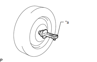
| *a | Gauge |
(a) Install a camber-caster-kingpin gauge or set the vehicle on a wheel alignment tester.
(b) Inspect the camber.
Standard Camber Inclination (Unloaded Vehicle):
| Tire Size | Camber Inclination | Right-left Difference |
|---|---|---|
| 225/65R17 | -1°15' +/-45' (-1.25° +/-0.75°) | 45' (0.75°) or less |
| 225/60R18 | -1°20' +/-45' (-1.33° +/-0.75°) | 45' (0.75°) or less |
- If the measured value is not within the specified range, inspect the suspension parts for damage and wear. Replace parts as necessary as the camber cannot be properly adjusted with any damaged or worn parts.
4. INSPECT TOE-IN
(a) Bounce the vehicle up and down at the corners to stabilize the suspension and inspect toe-in.
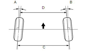
.png) | Front of the Vehicle |
Toe-in (Unloaded Vehicle):
| A + B C - D |
|---|
| A + B: 0°10' +/-10' (0.16° +/-0.16°) C - D: 2.0 +/-2.0 mm (0.08 +/-0.08 in.) |
HINT:
If the toe-in is not within the specified range, inspect the suspension parts and replace them if necessary.
5. ADJUST TOE-IN
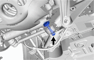
(a) Loosen the toe adjust cam nut.
| (b) Turn the adjust cams by an equal amount to adjust the toe-in. Toe-in (Unloaded Vehicle):
HINT:
|
|
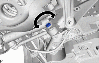
| (c) Tighten the toe adjust cam nut. Torque: 120 N·m {1224 kgf·cm, 89 ft·lbf} |
|
6. PLACE FRONT WHEELS FACING STRAIGHT AHEAD
7. PERFORM YAW RATE AND ACCELERATION SENSOR CALIBRATION
Click here
8. ADJUST FORWARD RECOGNITION CAMERA (w/ LANE TRACING ASSIST SYSTEM)
-
One time recognition:
Click here
-
Sequential recognition:
Click here
9. PERFORM INITIALIZATION
Click here
READ NEXT:
 Components
COMPONENTS ILLUSTRATION *1 FRONT AXLE ASSEMBLY LH *2 FRONT LOWER BALL JOINT ASSEMBLY LH *3 CLIP - - N*m (kgf*cm, ft.*lbf): Specified torque ● Non-reusable part
SEE MORE:
Disassembly
DISASSEMBLY CAUTION / NOTICE / HINT HINT:
Use the same procedure for the RH and LH sides.
The procedure listed below is for the LH side.
PROCEDURE 1. REMOVE REAR DOOR UPPER OUTSIDE MOULDING PAD (a) Remove the rear door upper outside moulding pad. 2. REMOVE REAR DOOR NO. 1 MOUL
Problem Symptoms Table
PROBLEM SYMPTOMS TABLE HINT: Use the table below to help determine the cause of problem symptoms. If multiple suspected areas are listed, the potential causes of the symptoms are listed in order of probability in the "Suspected Area" column of the table. Check each symptom by checking the suspected
