Lexus NX: Reassembly
REASSEMBLY
PROCEDURE
1. INSTALL NO. 2 STEERING RACK BOOT
| (a) Apply lithium soap base glycol grease to the inside of the steering rack end. |
|
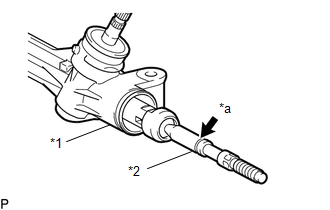
(b) Install the No. 2 steering rack boot to the groove on the rack housing.
NOTICE:
- Make sure that the boot is free of rust and foreign matter.
- Be careful not to damage or twist the boot.
2. INSTALL NO. 1 STEERING RACK BOOT
HINT:
Use the same procedure as for the No. 2 steering rack boot.
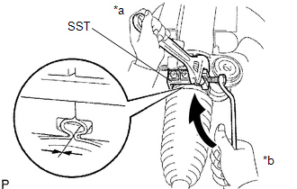
3. TIGHTEN NO. 2 STEERING RACK BOOT CLAMP
| (a) Using SST, tighten a new No. 2 steering rack boot clamp as shown in the illustration. SST: 09521-24010 Clearance: 3.0 mm (0.118 in.) or less NOTICE: Be careful not to damage or twist the boot. |
|
4. TIGHTEN NO. 1 STEERING RACK BOOT CLAMP
HINT:
Use the same procedure as for the No. 2 steering rack boot clamp.
5. INSTALL STEERING RACK BOOT CLIP
(a) Using pliers, install the 2 steering rack boot clips.
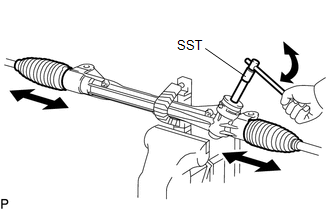
6. INSPECT STEERING GEAR ASSEMBLY
| (a) Using SST, rotate the pinion shaft to see if both the left and right steering rack boots expand and contract smoothly. SST: 09616-00011 HINT: If the result is not as specified, use new steering rack boot clamps and reinstall the steering rack boots. |
|
7. CONNECT TIE ROD END SUB-ASSEMBLY LH
| (a) Install the lock nut and tie rod end sub-assembly LH to the steering gear assembly so that the matchmarks align. HINT: After adjusting toe-in, tighten the lock nuts to the specified torque. |
|
8. CONNECT TIE ROD END SUB-ASSEMBLY RH
HINT:
Use the same procedure described for the LH side.
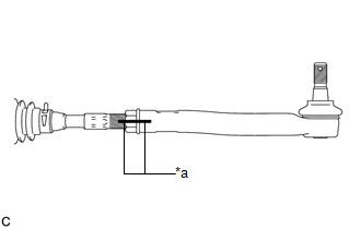
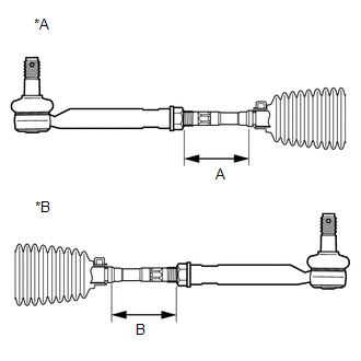
9. CHECK TIE ROD END SUB-ASSEMBLY
| (a) Adjust the tie rod end sub-assembly LH and RH so that distance A and distance B are within the specified ranges. Reference Values:
HINT:
|
|
READ NEXT:
 Installation
INSTALLATION PROCEDURE 1. INSTALL STEERING GEAR ASSEMBLY (a) Install the steering gear assembly to the front suspension crossmember with the 2 bolts and 2 nuts. Torque: 110 N·m {1122 kgf·cm, 81 ftÂ
SEE MORE:
Inverter Low-voltage Circuit
DESCRIPTION The cause of the malfunction may be the low-voltage circuit. Check whether there is an open circuit in the inverter +B low-voltage power source system or a problem in the communication between the hybrid vehicle control ECU and inverter. Related Parts Check Area Inspection Step
Mirror Heater does not Operate with Rear Defogger Switch
DESCRIPTION When therear window defogger switch (mirror heater switch) is operated, a mirror heater signal is sent to the air conditioning amplifier assembly via LIN communication. The air conditioning amplifier assembly sends the signal to the outer mirror control ECU assembly via CAN communication
