Lexus NX: Reassembly
REASSEMBLY
CAUTION / NOTICE / HINT
HINT:
- Use the same procedure for the RH and LH sides.
- The procedure listed below is for the LH side.
PROCEDURE
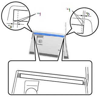
1. INSTALL NO. 3 MOULDING TAPE
(a) Clean the No. 3 moulding tape installation surface.
(1) When reusing the side mudguard LH, remove the double-sided tape remaining on the No. 3 moulding tape installation surface.
NOTICE:
- Installing the No. 3 moulding tape with some double-sided tape remaining may cause poor adhesion.
- Removing with a screwdriver, etc. may cause damage or poor adhesion.
(2) Clean the No. 3 moulding tape installation surface with a non-residue solvent.
(3) Apply primer to the No. 3 moulding tape installation area on the side mudguard LH.
NOTICE:
Do not apply too much primer.
(b) Remove the peeling paper on a new No. 3 moulding tape while making sure not to touch the adhesional surface.
| (c) Install a new No. 3 moulding tape in the position shown in the illustration. NOTICE:
|
|
READ NEXT:
 Installation
INSTALLATION CAUTION / NOTICE / HINT HINT:
Use the same procedure for the RH and LH sides.
The procedure listed below is for the LH side.
PROCEDURE 1. INSTALL SIDE MUDGUARD SUB-ASSEMBLY LH HIN
Components
COMPONENTS ILLUSTRATION *1 FRONT FENDER MOULDING SUB-ASSEMBLY LH - - ILLUSTRATION *1 NO. 1 MOULDING TAPE *2 NO. 2 MOULDING TAPE ● Non-reusable part - -
SEE MORE:
Installation
INSTALLATION PROCEDURE 1. INSTALL HOOD LOCK CONTROL CABLE ASSEMBLY (a) Tie the string that was passed through the engine compartment room to the end of the hood lock control cable assembly as shown in the illustration. HINT: Use a length of string long enough to pass through the engine compartmen
Telescopic Position Sensor or Telescopic Motor Circuit Malfunction (B2611)
DESCRIPTION The telescopic motor is operated by the power source voltage supplied from the multiplex tilt and telescopic ECU and slides the steering column forward and backward. The telescopic position sensor (Hall IC) in the telescopic motor detects the sliding position of the steering column in th
© 2016-2024 Copyright www.lexunx.com
