Lexus NX: Removal
REMOVAL
PROCEDURE
1. REMOVE ENGINE OIL LEVEL DIPSTICK GUIDE
| (a) Remove the engine oil level dipstick. |
|
(b) Remove the bolt and engine oil level dipstick guide.
(c) Remove the O-ring from the engine oil level dipstick guide.
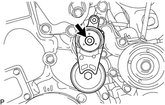
2. REMOVE V-RIBBED BELT TENSIONER ASSEMBLY
| (a) Remove the bolt and V-ribbed belt tensioner assembly. |
|
3. REMOVE COMPRESSOR ASSEMBLY WITH MOTOR
Click here .gif)
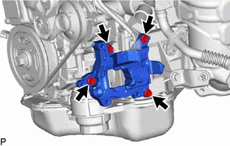
4. REMOVE NO. 1 COMPRESSOR MOUNTING BRACKET
| (a) Remove the 4 bolts and No. 1 compressor mounting bracket. |
|
5. REMOVE NO. 1 EXHAUST MANIFOLD HEAT INSULATOR
Click here
6. REMOVE NO. 2 EGR PIPE
Click here
7. REMOVE NO. 2 MANIFOLD STAY
Click here
8. REMOVE MANIFOLD STAY
Click here
9. REMOVE EXHAUST MANIFOLD CONVERTER SUB-ASSEMBLY
Click here
10. REMOVE THROTTLE WITH MOTOR BODY ASSEMBLY
Click here
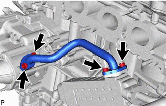
11. REMOVE WATER BY-PASS PIPE
| (a) Remove the 4 bolts, water by-pass pipe and 2 gaskets. |
|
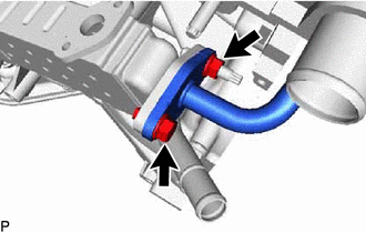
12. REMOVE EGR COOLER ASSEMBLY
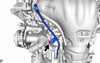
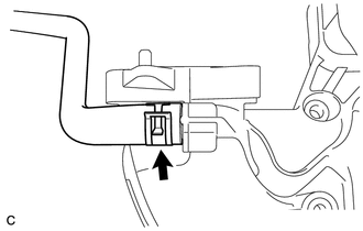
| (a) Slide the hose clamp and disconnect the No. 5 water by-pass hose from the EGR cooler assembly. |
|
.png)
| (b) Remove the bolt and nut, and disconnect the No. 1 EGR pipe from the EGR cooler assembly. |
|
| (c) Remove the bolt, nut and EGR cooler assembly. |
|
.png)
(d) Remove the gasket from the No. 1 EGR pipe.
13. REMOVE EGR VALVE ASSEMBLY
Click here
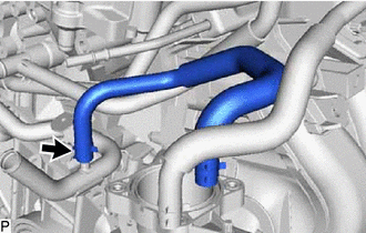
14. REMOVE NO. 3 WATER BY-PASS HOSE
| (a) Slide the hose clamp and remove the No. 3 water by-pass hose. |
|
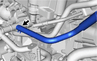
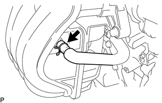
15. REMOVE NO. 1 WATER BY-PASS HOSE
| (a) Slide the hose clamp and remove the No. 1 water by-pass hose from the cylinder block. |
|
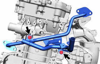
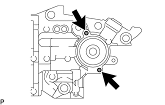
16. REMOVE NO. 1 EGR PIPE
| (a) Remove the 2 bolts and No. 1 EGR pipe. |
|
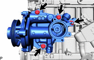
17. REMOVE ENGINE WATER PUMP ASSEMBLY
Click here
18. REMOVE WATER INLET
Click here
19. REMOVE THERMOSTAT
Click here
20. REMOVE OIL COOLER ASSEMBLY
Click here
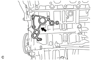
21. REMOVE WATER INLET HOUSING
| (a) Remove the 3 bolts, nut and water inlet housing from the cylinder block. |
|
| (b) Remove the gasket. |
|
| (c) Using an E6 "TORX" socket wrench, remove the 2 stud bolts from the water inlet housing. NOTICE: If a stud bolt is deformed or its thread is damaged, replace it. |
|
22. REMOVE INTAKE MANIFOLD
| (a) Slide the clamp and disconnect the No. 2 PCV hose from the intake manifold. |
|
| (b) Slide the clamp and disconnect the purge line hose from the intake manifold. |
|
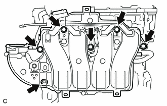
| (c) Remove the 6 bolts and intake manifold. |
|
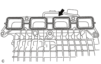
| (d) Remove the No. 1 intake manifold to head gasket from the intake manifold. |
|
23. REMOVE FUEL DELIVERY PIPE
Click here
24. REMOVE INJECTOR VIBRATION INSULATOR
Click here
25. REMOVE SENSOR WIRE
| (a) Disconnect the knock control sensor connector. |
|
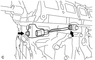
(b) Remove the bolt and sensor wire.
26. REMOVE IGNITION COIL ASSEMBLY
Click here
READ NEXT:
 Disassembly
DISASSEMBLY PROCEDURE 1. REMOVE ENGINE COVER JOINT (a) Remove the 3 engine cover joints. 2. REMOVE SPARK PLUG Click here 3. REMOVE KNOCK CONTROL SENSOR Click here 4. REMOVE ENGINE C
Inspection
INSPECTION PROCEDURE 1. INSPECT NO. 1 VALVE ROCKER ARM SUB-ASSEMBLY (a) Turn the roller by hand and check that it turns smoothly. If the roller does not turn smoothly, replace the No. 1 valve rocker a
Reassembly
REASSEMBLY PROCEDURE 1. INSTALL STIFFENING CRANKCASE RING PIN NOTICE: It is not necessary to remove the ring pin unless it is being replaced. *a Protrusion Height (a) Using a plastic-faced ha
SEE MORE:
Open in Inside Luggage Compartment Electrical Key Oscillator Circuit (B27A7)
DESCRIPTION The certification ECU (smart key ECU assembly) generates a request signal and transmits the signal to the No. 3 indoor electrical key antenna assembly (inside luggage). For the No. 3 indoor electrical key antenna assembly (inside luggage) to detect when the electrical key transmitter sub
Ambient Temperature Sensor
ComponentsCOMPONENTS ILLUSTRATION *1 THERMISTOR ASSEMBLY (AMBIENT TEMPERATURE SENSOR) - - RemovalREMOVAL PROCEDURE 1. REMOVE FRONT BUMPER ASSEMBLY (a) for Sport Package: Click here (b) except Sport Package: Click here 2. REMOVE THERMISTOR ASSEMBLY (AMBIENT TEMPERATURE SENSOR) (
