Lexus NX: Removal
REMOVAL
CAUTION / NOTICE / HINT
NOTICE:
- Do not replace the spiral with sensor cable sub-assembly with the battery connected and the power switch on (IG).
- Do not rotate the spiral with sensor cable sub-assembly when the following conditions are met: 1) The steering wheel is removed, 2) the battery is connected,and 3) the power switch is on (IG).
- Ensure that the steering wheel is installed and aligned straight when inspecting the steering sensor.
PROCEDURE
1. PLACE FRONT WHEELS FACING STRAIGHT AHEAD
2. REMOVE STEERING PAD
Click here .gif)
3. REMOVE STEERING WHEEL ASSEMBLY
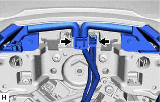
| (a) Disconnect 2 connectors from the spiral cable with sensor sub-assembly. |
|
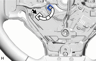
| (b) Disconnect the connector. |
|
| (c) Remove the steering wheel assembly set nut. |
|
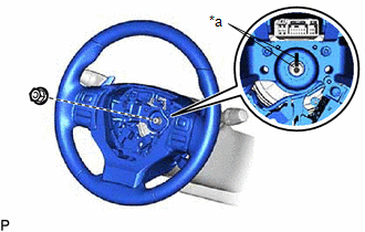
(d) Put matchmarks on the steering wheel assembly and steering main shaft.
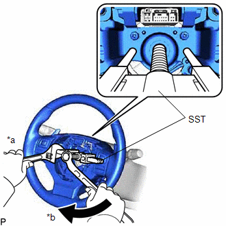
| (e) Using SST, remove the steering wheel assembly. SST: 09950-50013 09951-05010 09952-05010 09953-05020 09954-05021 NOTICE: Apply a small amount of grease to the threads and tip of SST (09953-05020) before use. |
|
4. REMOVE CRUISE CONTROL MAIN SWITCH
Click here
5. REMOVE STEERING PAD SWITCH ASSEMBLY
Click here
6. REMOVE SHIFT PADDLE SWITCH (TRANSMISSION SHIFT SWITCH ASSEMBLY)
Click here
7. REMOVE STEERING WHEEL HEATER CONTROL ASSEMBLY (w/ Steering Heater)
Click here
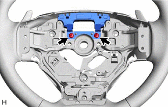
8. REMOVE STEERING SHAKE DAMPER
| (a) Remove the 2 screws and steering shake damper from the steering wheel assembly. |
|
READ NEXT:
 Installation
INSTALLATION CAUTION / NOTICE / HINT NOTICE:
Do not replace the spiral with sensor cable sub-assembly with the battery connected and the power switch on (IG).
Do not rotate the spiral with sensor
Components
COMPONENTS ILLUSTRATION *1 DECK FLOOR BOX LH *2 REAR DECK FLOOR BOX *3 NO. 3 DECK BOARD SUB-ASSEMBLY *4 NEGATIVE AUXILIARY BATTERY TERMINAL N*m (kgf*cm, ft.*lbf): Specified
SEE MORE:
Odo/Trip Switch Malfunction
DESCRIPTION The ODO/TRIP display of the combination meter changes each time the trip switch is pressed. WIRING DIAGRAM CAUTION / NOTICE / HINT NOTICE: When replacing the combination meter assembly, make sure to replace it with a new one. PROCEDURE 1. READ VALUE USING TECHSTREAM (ODO/TRIP CHAN
Lost Communication with Gateway Module (Main Body ECU) (U1002)
DESCRIPTION
The main body ECU (multiplex network body ECU) will store this DTC when no signals can be received from the ECUs that have been memorized as those that are connected to sub bus 1.
When the main body ECU (multiplex network body ECU) receives a response signal from the ECUs connected
