Lexus NX: Removal
REMOVAL
PROCEDURE
1. PRECAUTION
NOTICE:
After turning the power switch is turned off, there may be a waiting time before disconnecting the auxiliary negative (-) battery terminal.
Click here .gif)
2. CUSTOMIZE POWER TILT AND POWER TELESCOPIC STEERING COLUMN SYSTEM
(a) Disable the auto tilt away function by changing the customize parameter.
Click here
NOTICE:
Record the current customize parameter setting (whether the auto tilt away function is enabled or disabled) in order to restore the current setting after finishing the operation.
HINT:
Performing the above operation causes the auto tilt away function to be disabled when the power switch is turned off.
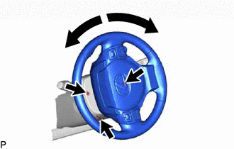
(b) Turn the power switch on (IG). Operate the tilt and telescopic switch to fully extend and lower the steering column assembly.
3. REMOVE NO. 3 DECK BOARD SUB-ASSEMBLY
Click here
4. REMOVE REAR DECK FLOOR BOX
Click here
5. REMOVE DECK FLOOR BOX LH
Click here
6. DISCONNECT CABLE FROM NEGATIVE AUXILIARY BATTERY TERMINAL
7. ALIGN FRONT WHEELS FACING STRAIGHT AHEAD
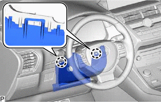
8. REMOVE LOWER STEERING COLUMN COVER
| (a) Remove the 3 screws. |
|
| (b) Detach the 2 claws and remove the lower steering column cover. NOTICE: Do not damage the tilt and telescopic switch. |
|
9. REMOVE TILT AND TELESCOPIC SWITCH
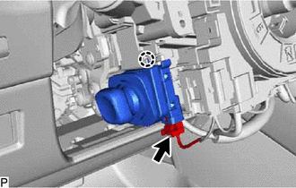
(a) Disconnect the connector.
(b) Detach the claw and pull out the tilt and telescopic switch.
NOTICE:
Pushing on the claw too hard will break the claw.
READ NEXT:
 Inspection
INSPECTION PROCEDURE 1. INSPECT TILT AND TELESCOPIC SWITCH (a) Measure the resistance according to the value(s) in the table below. Standard Resistance: Tester Connection Switch Condition S
Installation
INSTALLATION PROCEDURE 1. INSTALL TILT AND TELESCOPIC SWITCH (a) Attach the claw to install the tilt and telescopic switch. (b) Connect the connector. 2. INSTALL LOWER STEERING COLUMN COVER (a) Attach
SEE MORE:
Security Horn Assembly
ComponentsCOMPONENTS ILLUSTRATION *1 SECURITY HORN ASSEMBLY - - N*m (kgf*cm, ft.*lbf): Specified torque - - RemovalREMOVAL PROCEDURE 1. REMOVE SECURITY HORN ASSEMBLY (a) Remove the bolt and detach the guide. (b) Disconnect the connector and remove the securit
Tires
Replace or rotate tires in accordance
with maintenance schedules
and treadwear.
Checking tires
Check if the treadwear indicators are
showing on the tires. Also check the
tires for uneven wear, such as excessive
wear on one side of the tread.
Check the spare tire condition and
pressure if
