Lexus NX: Removal
REMOVAL
CAUTION / NOTICE / HINT
HINT:
- Use the same procedure for the RH and LH sides.
- The procedure listed below is for the LH side.
PROCEDURE
1. REMOVE REAR WHEEL
Click here .gif)
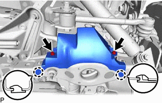
2. REMOVE REAR SUSPENSION ARM COVER LH
| (a) Remove the 2 bolts and disengage the 2 claws to remove the rear suspension arm cover LH from the rear No. 2 suspension arm assembly LH. |
|
3. REMOVE REAR HEIGHT CONTROL SENSOR SUB-ASSEMBLY LH
Click here
4. REMOVE REAR SHOCK ABSORBER ASSEMBLY LH
Click here
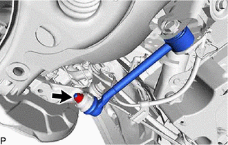
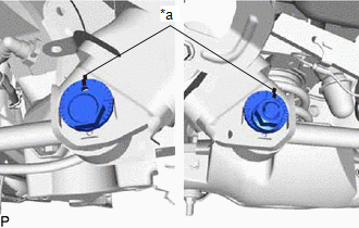
5. REMOVE REAR NO. 1 SUSPENSION ARM ASSEMBLY LH
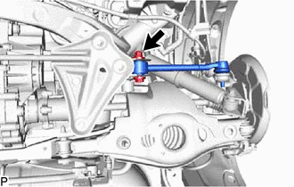
| (a) Remove the nut from the rear axle carrier. |
|
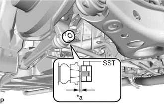
| (b) Install SST to the rear No. 1 suspension arm as shown in the illustration. SST: 09960-20010 09961-02060 NOTICE: Make sure that the clearance measurement between SST and the rear axle assembly is 1 mm (0.0394 in.). HINT: Use 2 SST of the same type. |
|
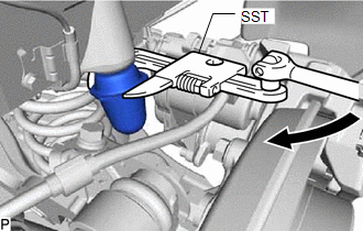
(c) Using SST, disconnect the rear No. 1 suspension arm from the rear axle carrier as shown in the illustration.
SST: 09960-20010
09961-02010
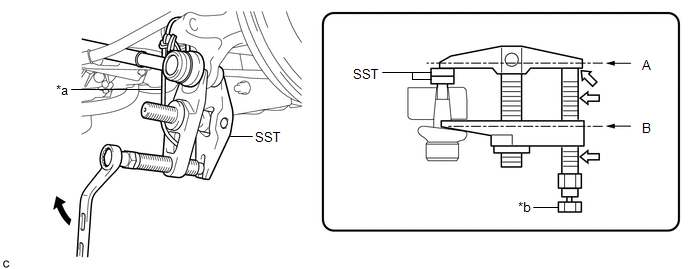
| *a | Tie the string so there is no slack | *b | Place the wrench here |
.png) | Turn | .png) | Molybdenum grease |
CAUTION:
Apply molybdenum grease to the threads and end of SST bolt.
NOTICE:
- Install SST so that A and B are parallel.
- Be sure to turn the part indicated in the illustration with a wrench.
- Do not damage the front lower ball joint dust cover.
- Be sure to tie the string of SST to the vehicle to prevent SST from dropping.
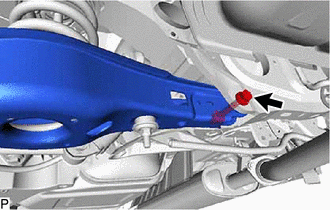
| (d) Put matchmarks on the rear suspension toe adjust cam, No. 2 camber adjust cam and rear suspension member. |
|
| (e) Remove the nut, No. 2 camber adjust cam, rear suspension toe adjust cam and rear No. 1 suspension arm assembly LH. |
|
6. REMOVE REAR STABILIZER LINK ASSEMBLY LH
Click here
7. LOOSEN REAR NO. 2 SUSPENSION ARM ASSEMBLY LH
Click here
8. REMOVE REAR COIL SPRING LH
Click here
9. REMOVE REAR UPPER COIL SPRING INSULATOR LH
Click here
10. REMOVE REAR LOWER COIL SPRING INSULATOR LH
Click here
11. REMOVE REAR NO. 2 SUSPENSION ARM ASSEMBLY LH
(a) Remove the bolt, nut and rear No. 2 suspension arm from the suspension member.
NOTICE:
Since a stopper nut is used, loosen the bolt.
12. REMOVE REAR NO. 1 SPRING BUMPER LH
| (a) Using SST, remove the rear No. 1 spring bumper LH. SST: 09922-10010 |
|
READ NEXT:
 Inspection
INSPECTION CAUTION / NOTICE / HINT HINT:
Use the same procedure for the RH and LH sides.
The procedure listed below is for the LH side.
PROCEDURE 1. INSPECT REAR NO. 1 SUSPENSION ARM ASSEMBLY
Installation
INSTALLATION CAUTION / NOTICE / HINT HINT:
Use the same procedure for the RH and LH sides.
The procedure listed below is for the LH side.
PROCEDURE 1. INSTALL REAR NO. 1 SPRING BUMPER LH (a
SEE MORE:
List of storage features
Location of the storage features
Glove box
Bottle holders
Console box
Cup holders
Auxiliary box
WARNING
■Items that should not be left in the
vehicle
Do not leave glasses, lighters or spray
cans in the storage spaces, as this may
cause the following when cabin temperature
Disassembly
DISASSEMBLY PROCEDURE 1. REMOVE GLOVE COMPARTMENT DOOR CHECK CUSHION HINT: Use the same procedure for both glove compartment door check cushions. (a) Using a screwdriver, detach the 3 claws and remove the glove compartment door check cushion. HINT: Tape the screwdriver tip before use.
