Lexus NX: Removal
REMOVAL
PROCEDURE
1. REMOVE REAR BUMPER COVER
Click here .gif)
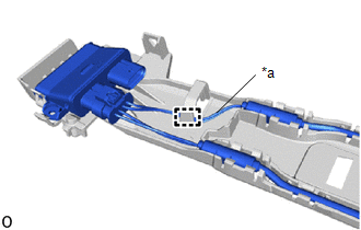
2. REMOVE KICK DOOR CONTROL BRACKET
| (a) Disconnect the connector and detach the 2 wire harness clamps. NOTICE: Do not touch the terminal of the kick door control sensor connector. |
|
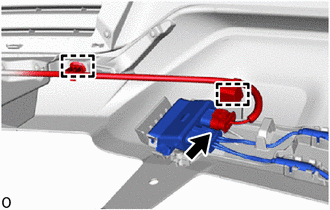
| (b) Remove the screw. |
|
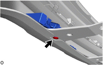
(c) Remove the 3 outside moulding retainers.
(d) Detach the 3 guides and remove the kick door control bracket together with the kick door control sensor as shown in the illustration.
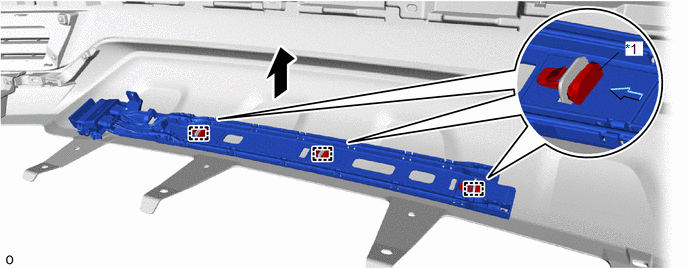
| *1 | Outside Moulding Retainer | - | - |
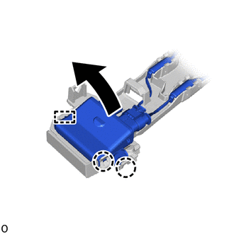
3. REMOVE KICK DOOR CONTROL SENSOR
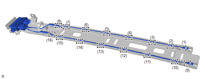
(a) Detach the 16 claws in the order shown in the illustration and disconnect the antenna.
| (b) Detach the clamp and disconnect the wire (red) from the kick door control bracket. NOTICE:
|
|
| (c) Detach the 2 claws and guide, and remove the kick door control sensor from the kick door control bracket as shown in the illustration. NOTICE:
|
|
READ NEXT:
 Installation
INSTALLATION PROCEDURE 1. INSTALL KICK DOOR CONTROL SENSOR (a) Insert the guide, attach the 2 claws and install the kick door control sensor to the kick door control bracket as shown in the illustr
Power Back Door Control Switch
ComponentsCOMPONENTS ILLUSTRATION *1 BACK DOOR CONTROL SWITCH *2 PULL HANDLE RemovalREMOVAL PROCEDURE 1. REMOVE PULL HANDLE Click here 2. REMOVE BACK DOOR CONTROL SWITCH (a) Detach
SEE MORE:
Short to +B in Outer Mirror Indicator(Slave) (C1AB1)
DESCRIPTION This DTC is stored when the blind spot monitor sensor RH detects a +B short in the outer rear view mirror indicator RH. DTC No. Detection Item DTC Detection Condition Trouble Area Note C1AB1 Short to +B in Outer Mirror Indicator(Slave) Both of the following conditions
Drive Motor "A" Control Module (P0A1B-554,P0A1C-169)
DTC SUMMARY MALFUNCTION DESCRIPTION These DTCs indicate that a large current flowed in the boost converter. The cause of this malfunction may be one of the following: Internal inverter malfunction
Inverter internal circuit malfunction
Malfunction in ECU that controls the inverter
DESCRIPTION
