Lexus NX: Removal
REMOVAL
CAUTION / NOTICE / HINT
HINT:
- Use the same procedure for the RH and LH sides.
- The procedure listed below is for the LH side.
PROCEDURE
1. PRECAUTION
NOTICE:
After the power switch off is turned off, there may be a waiting time before disconnecting the auxiliary negative (-) battery terminal.
Click here .gif)
2. REMOVE NO. 3 DECK BOARD SUB-ASSEMBLY
Click here
3. REMOVE REAR DECK FLOOR BOX
Click here
4. REMOVE DECK FLOOR BOX LH
Click here
5. DISCONNECT CABLE FROM NEGATIVE AUXILIARY BATTERY TERMINAL
NOTICE:
When disconnecting the cable, some systems need to be initialized after the cable is reconnected.
Click here
6. REMOVE REAR DOOR TRIM COVER LH
Click here
7. REMOVE REAR DOOR INSIDE HANDLE BEZEL PLUG LH
Click here
8. REMOVE REAR POWER WINDOW REGULATOR SWITCH ASSEMBLY WITH REAR DOOR ARMREST BASE PANEL
Click here
9. REMOVE REAR DOOR TRIM BOARD SUB-ASSEMBLY LH
Click here
10. REMOVE REAR DOOR INNER GLASS WEATHERSTRIP LH
Click here
11. REMOVE REAR DOOR ARMREST SET BRACKET LH
Click here
12. REMOVE REAR DOOR SERVICE HOLE COVER LH
Click here
13. REMOVE REAR DOOR GLASS RUN LH
Click here
14. REMOVE REAR DOOR REAR LOWER WINDOW FRAME SUB-ASSEMBLY LH
Click here
15. REMOVE REAR DOOR REAR GUIDE SEAL LH
Click here
16. REMOVE REAR DOOR GLASS SUB-ASSEMBLY LH
Click here
17. DISCONNECT REAR DOOR CHECK ASSEMBLY LH
Click here
18. REMOVE REAR DOOR WEATHERSTRIP LH
Click here
19. REMOVE REAR DOOR FRAME GARNISH LH
Click here
20. REMOVE REAR DOOR BELT MOULDING ASSEMBLY LH
Click here
21. REMOVE REAR DOOR FRONT WINDOW FRAME MOULDING LH
HINT:
When removing rear door front window frame moulding LH, heat the rear door panel and rear door front window frame moulding LH using a heat light.
Standard:
| Item | Temperature |
|---|---|
| Rear Door Panel | 40 to 60°C (104 to 140°F) |
| Rear Door Front Window Frame Moulding LH | 20 to 30°C (68 to 86°F) |
NOTICE:
Do not heat the rear door panel and rear door front window frame moulding LH excessively.
(a) Put protective tape around the rear door front window frame moulding LH.
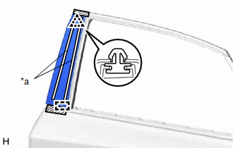
| *a | Double-sided Tape |
.png) | Protective Tape |
(b) Using moulding remover D, detach the clip.
(c) Detach the double-sided tape, and then detach the guide and remove the rear door front window frame moulding LH.
22. REMOVE REAR DOOR UPPER WINDOW FRAME MOULDING LH
(a) Put a 4 mm (0.157 in.) drill bit into a drill.
(b) Wind tape around the drill bit approximately 5 mm (0.197 in.) from the tip of the drill as shown in the illustration.
HINT:
Tape the 4 mm (0.157 in.) drill bit to prevent the drill bit from going too deep.
(c) Lightly press the drill against the 4 rivets and drill off the flanges of the 4 rivets.
CAUTION:
Be careful of the drilled rivet as it may become hot.
NOTICE:
- Pressing the drill too firmly will cause the rivet to turn and result in the rivet not being drilled through.
- Do not pry the rivet with the drill because this may cause damage to the installation holes of the rivet or the drill bit.
(d) Remove the rear door upper window frame moulding LH.
(e) Using a vacuum cleaner, remove the rivet fragments and shavings from the drilled area.
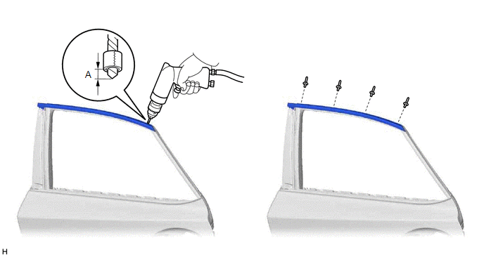
Standard:
| Area | Specified Condition |
|---|---|
| A | 5 mm (0.197 in.) |
23. REMOVE REAR DOOR REAR WINDOW FRAME MOULDING LH
(a) Put a 4 mm (0.157 in.) drill bit into a drill.
(b) Wind tape around the drill bit approximately 5 mm (0.197 in.) from the tip of the drill as shown in the illustration.
HINT:
Tape the 4 mm (0.157 in.) drill bit to prevent the drill bit from going too deep.
(c) Lightly press the drill against the 3 rivets and drill off the flanges of the 3 rivets.
CAUTION:
Be careful of the drilled rivet as it may become hot.
NOTICE:
- Pressing the drill too firmly will cause the rivet to turn and result in the rivet not being drilled through.
- Do not pry the rivet with the drill because this may cause damage to the installation holes of the rivet or the drill bit.
(d) Remove the rear door rear window frame moulding LH.
(e) Using a vacuum cleaner, remove the rivet fragments and shavings from the drilled area.
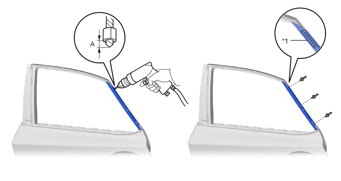
| *1 | Caulking Sponge | - | - |
Standard:
| Area | Specified Condition |
|---|---|
| A | 5 mm (0.197 in.) |
READ NEXT:
 Installation
INSTALLATION CAUTION / NOTICE / HINT HINT:
Use the same procedure for the RH and LH sides.
The procedure listed below is for the LH side.
PROCEDURE 1. INSTALL REAR DOOR REAR WINDOW FRAME MOULD
Components
COMPONENTS ILLUSTRATION *1 BACK DOOR CENTER GARNISH *2 REAR SIDE SPOILER SUB-ASSEMBLY LH *3 REAR SIDE SPOILER SUB-ASSEMBLY RH *4 REAR SPOILER ASSEMBLY *5 HOLE PLUG - -
SEE MORE:
Removal
REMOVAL CAUTION / NOTICE / HINT HINT:
Use the same procedure for the RH and LH sides.
The procedure described below is for the LH side.
PROCEDURE 1. REMOVE FRONT BUMPER ASSEMBLY Click here 2. REMOVE FOG LIGHT ASSEMBLY LH (a) Remove the 2 screws. (b) Detach the guide and remo
DC / DC Converter Status Circuit Low Input (P0A09-591)
DESCRIPTION The DC/DC converter varies output voltage based on voltage change signals (VLO signal line) received from the hybrid vehicle control ECU. If the vehicle is being driven with an inoperative DC/DC converter, the voltage of the auxiliary battery will drop, which will prevent the continued o
