Lexus NX: Removal
REMOVAL
PROCEDURE
1. REMOVE NO. 3 DECK BOARD SUB-ASSEMBLY
Click here .gif)
2. REMOVE REAR DECK FLOOR BOX
Click here
3. REMOVE DECK FLOOR BOX LH
Click here
4. PRECAUTION
CAUTION:
Be sure to read Precaution thoroughly before servicing.
Click here
NOTICE:
After the power switch is turned off, there may be a waiting time before disconnecting the negative (-) auxiliary battery terminal.
Click here
5. DISCONNECT CABLE FROM NEGATIVE AUXILIARY BATTERY TERMINAL
CAUTION:
Wait at least 90 seconds after disconnecting the cable from the negative (-) auxiliary battery terminal to disable the SRS system.
(a) Loosen the nut and disconnect the cable from the negative (-) auxiliary battery terminal.
6. PLACE FRONT WHEELS FACING STRAIGHT AHEAD
7. REMOVE STEERING WHEEL ASSEMBLY
Click here
8. INSPECT SPIRAL WITH SENSOR CABLE SUB-ASSEMBLY
(a) Check that the front wheels are facing straight ahead.
(b) Check that the spiral with sensor cable sub-assembly is center position.
OK:
The connector is at the top.
The matchmarks are aligned.
The top of the flat cable U-turn can be checked from the check window.
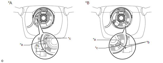
| *A | w/o Steering Heater | *B | w/ Steering Heater |
| *a | Check Window | *b | Matchmark |
| *c | Top of Flat Cable U-turn | - | - |
NOTICE:
If the result is not as specified, it is possible that the spiral cable sub-assembly is broken. Replace the spiral cable sub-assembly with a new one.
9. REMOVE LOWER STEERING COLUMN COVER
Click here
10. REMOVE UPPER STEERING COLUMN COVER
Click here
11. REMOVE SPIRAL WITH SENSOR CABLE SUB-ASSEMBLY
NOTICE:
- Do not replace the spiral with sensor cable sub-assembly with the auxiliary battery connected and the power switch on (IG).
- Do not rotate the spiral with sensor cable sub-assembly with the battery connected and the power switch on (IG).
- When rotating the spiral with sensor cable sub-assembly to check the operation of the sub-assembly (checking for abnormal noise, checking the Data List, etc.), make sure to perform the inspection with the steering wheel assembly installed.
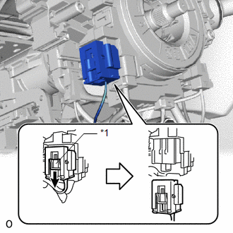
| (a) Slide the slider to release the lock, and then disconnect the airbag connector. NOTICE: When disconnecting any airbag connector, take care not to damage the airbag wire harness. |
|
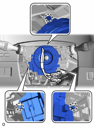
(b) Disconnect each connector.
| (c) Detach the 3 claws and remove the spiral with sensor cable sub-assembly. |
|
12. REMOVE STEERING SENSOR
NOTICE:
- Remove the steering sensor from the spiral cable sub-assembly only when replacing the spiral cable sub-assembly.
- Removing the steering sensor from the spiral cable sub-assembly without using a lock pin may result in a misaligned center position of the steering sensor. Therefore, make sure to use the lock pin provided with a new spiral cable when removing the steering sensor from the spiral cable sub-assembly.
| (a) Install the lock pin to the steering sensor. NOTICE:
|
|
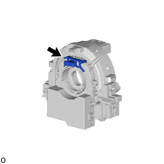
(b) Remove the steering sensor from the spiral cable sub-assembly.
Click here
READ NEXT:
 Inspection
INSPECTION PROCEDURE 1. INSPECT SPIRAL WITH SENSOR CABLE SUB-ASSEMBLY NOTICE:
Do not remove the steering sensor from the spiral with sensor cable sub-assembly.
As the spiral with sensor cable sub
Components
COMPONENTS ILLUSTRATION *1 DECK FLOOR BOX LH *2 NO. 3 DECK BOARD SUB-ASSEMBLY *3 REAR DECK FLOOR BOX *4 AUXILIARY BATTERY NEGATIVE TERMINAL N*m (kgf*cm, ft.*lbf): Specified
SEE MORE:
Front Right Center Sensor (C1AE3)
DESCRIPTION The front center ultrasonic sensor (FRC sensor) is installed to the front bumper. The clearance warning ECU assembly detects obstacles based on signals received from the front center ultrasonic sensor (FRC sensor). If the front center ultrasonic sensor (FRC sensor) has an open circuit or
Parts Location
PARTS LOCATION ILLUSTRATION *A w/o Navigation System *B w/ Navigation System *1 FRONT NO. 1 SPEAKER ASSEMBLY RH *2 FRONT NO. 2 SPEAKER ASSEMBLY RH *3 TELEPHONE MICROPHONE ASSEMBLY *4 MAP LIGHT ASSEMBLY - MANUAL (SOS) SWITCH *5 NO. 2 ENGINE ROOM RELAY BLOCK - DCM F
