Lexus NX: Removal
REMOVAL
PROCEDURE
1. REMOVE DECK BOARD ASSEMBLY
Click here .gif)
2. REMOVE NO. 3 DECK BOARD SUB-ASSEMBLY
Click here
3. REMOVE REAR DECK FLOOR BOX
Click here
4. REMOVE DECK FLOOR BOX LH
Click here
5. PRECAUTION
CAUTION:
Be sure to read Precaution thoroughly before serving.
Click here
NOTICE:
After turning the power switch off, there may be a waiting time before disconnecting the negative (-) auxiliary battery terminal.
Click here
6. DISCONNECT CABLE FROM NEGATIVE AUXILIARY BATTERY TERMINAL
CAUTION:
- Wait at least 90 seconds after disconnecting the cable from the negative (-) auxiliary battery terminal to disable the SRS system.
- If the airbag deploys for any reason. it may cause a serious accident.
7. REMOVE INSTRUMENT PANEL FINISH PLATE
Click here
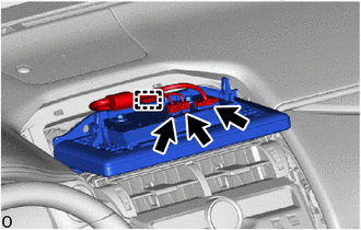
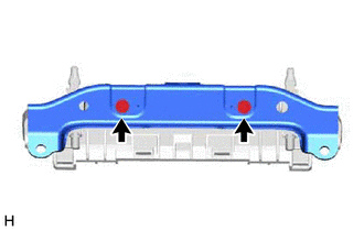
8. REMOVE MULTI-DISPLAY ASSEMBLY WITH BRACKET
(a) for 8 inch:
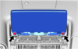
(1) Remove the 2 bolts.
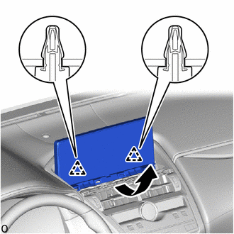
| (2) Move the multi-display assembly with bracket as indicated by the arrow shown in the illustration to detach the 2 clips. |
|

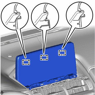
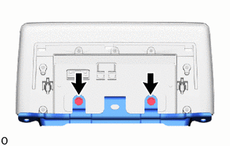
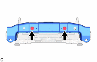
| (3) Detach the 3 guides. |
|
| (4) Disconnect the 3 connector. |
|

(5) Detach the clamp and remove the multi-display assembly with bracket.
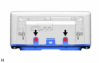
(b) for 10.3 inch:
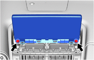
(1) Remove the 2 bolts.
| (2) Move the multi-display assembly with bracket as indicated by the arrow shown in the illustration to detach the 2 clips. |
|
| (3) Detach the 3 guides. |
|

| (4) Disconnect the 3 connector. |
|
(5) Detach the clamp and remove the multi-display assembly with bracket.
9. REMOVE MULTI-DISPLAY CONTROLLER BRACKET A
(a) for 8 inch:
| (1) Remove the 2 screws. |
|
| (2) Remove the 2 screws and multi-display controller bracket A. |
|
(b) for 10.3 inch:
| (1) Remove the 2 screws. |
|
| (2) Remove the 2 screws and multi-display controller bracket A. |
|
10. REMOVE MULTI-DISPLAY ASSEMBLY
READ NEXT:
 Installation
INSTALLATION PROCEDURE 1. INSTALL MULTI-DISPLAY ASSEMBLY 2. INSTALL MULTI-DISPLAY CONTROLLER BRACKET A (a) for 8 inch: (1) Temporarily install the multi-display controller bracket A with the 2 scre
Components
COMPONENTS ILLUSTRATION *1 NAVIGATION ANTENNA ASSEMBLY WITH BRACKET *2 NO. 1 HEATER TO REGISTER DUCT SUB-ASSEMBLY *3 UPPER INSTRUMENT PANEL SUB-ASSEMBLY - - ILLUSTRATION *1
SEE MORE:
Reassembly
REASSEMBLY CAUTION / NOTICE / HINT HINT:
A bolt without a torque specification is shown in the standard bolt chart.
Click here PROCEDURE 1. INSTALL CUSHION (a) Install the cushion. HINT: Use the same procedure as for the LH side. 2. INSTALL BACK DOOR LOWER STOPPER LH (a) When replacing the b
Data List / Active Test
DATA LIST / ACTIVE TEST DATA LIST HINT: Using the Techstream to read the Data List allows the values or states of switches, sensors, actuators and other items to be read without removing any parts. This non-intrusive inspection can be very useful because intermittent conditions or signals may be dis
