Lexus NX: Reassembly
REASSEMBLY
CAUTION / NOTICE / HINT
HINT:
-
A bolt without a torque specification is shown in the standard bolt chart.
Click here
.gif)
PROCEDURE
1. INSTALL CUSHION
(a) Install the cushion.
HINT:
Use the same procedure as for the LH side.
2. INSTALL BACK DOOR LOWER STOPPER LH
(a) When replacing the bolt with a new one:
(1) Clean the threaded portion on the vehicle body with non-residue solvent.
(b) When reusing the back door stay bolt:
(1) Clean the threaded portion on the vehicle body with non-residue solvent.
(2) Apply adhesive to the threads of the bolt.
Adhesive:
Toyota Genuine Adhesive 1324, Three Bond 1324 or equivalent
(c) Install the back door lower stopper LH with the bolt.
3. INSTALL BACK DOOR LOWER STOPPER
HINT:
Use the same procedure as for the LH side.
4. INSTALL BACK DOOR WEIGHT
(a) Attach the guide to install the back door weight.
(b) Install the 3 bolts.
Torque:
8.0 N·m {82 kgf·cm, 71 in·lbf}
5. INSTALL REAR WIPER MOTOR ASSEMBLY
Click here
6. INSTALL BACK DOOR LOCK ASSEMBLY (w/ Power Back Door)
Click here
7. INSTALL BACK DOOR LOCK ASSEMBLY (w/o Power Back Door)
Click here
8. INSTALL POWER BACK DOOR WARNING BUZZER (w/ Power Back Door)
Click here
9. INSTALL REAR NO. 3 SPEAKER ASSEMBLY (w/ Back Door Speaker)
Click here
10. INSTALL MULTIPLEX NETWORK DOOR ECU (w/ Power Back Door)
Click here
11. INSTALL REAR TELEVISION CAMERA ASSEMBLY (w/ Parking Assist Monitor System)
Click here
12. INSTALL LICENSE PLATE LIGHT ASSEMBLY LH
Click here
13. INSTALL LICENSE PLATE LIGHT ASSEMBLY RH
HINT:
Use the same procedure as for the LH side.
14. INSTALL BACK DOOR OPENER SWITCH ASSEMBLY
Click here
15. INSTALL BACK DOOR OUTSIDE GARNISH SUB-ASSEMBLY
Click here
16. INSTALL REAR LIGHT ASSEMBLY LH
Click here
17. INSTALL REAR LIGHT ASSEMBLY RH
HINT:
Use the same procedure as for the LH side.
18. INSTALL REAR WASHER NOZZLE
Click here
19. INSTALL REAR SPOILER ASSEMBLY
Click here
20. INSTALL POWER BACK DOOR SENSOR ASSEMBLY LH (w/ Power Back Door)
Click here
21. INSTALL POWER BACK DOOR SENSOR ASSEMBLY RH (w/ Power Back Door)
HINT:
Use the same procedure as for the LH side.
22. INSTALL NO. 1 AMPLIFIER ANTENNA ASSEMBLY
Click here
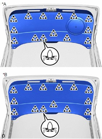
23. INSTALL BACK DOOR TRIM BOARD ASSEMBLY
| (a) Attach the 14 clips to install the back door trim board assembly. |
|
24. INSTALL BACK DOOR LOCK COVER (w/ Power Back Door)
(a) Clean the back door panel surface.
(1) Remove the double-sided tape from the rear door panel surface.
(2) Wipe off any tape adhesive residue with cleaner.
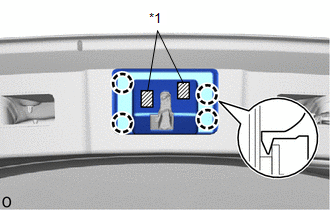
(b) Install a new back door lock cover.
(1) Remove the peeling paper from the face of the back door lock cover.
HINT:
After removing the peeling paper, keep the exposed adhesive free from foreign matter.
| (2) Attach the 4 claws to install the back door lock cover. HINT: Press the back door lock cover firmly to install it. |
|
25. INSTALL BACK DOOR LOCK COVER (w/o Power Back Door)
(a) Clean the back door panel surface.
(1) Remove the double-sided tape from the rear door panel surface.
(2) Wipe off any tape adhesive residue with cleaner.
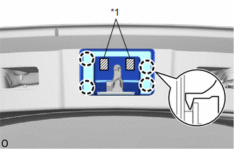
(b) Install a new back door lock cover.
(1) Remove the peeling paper from the face of the back door lock cover.
HINT:
After removing the peeling paper, keep the exposed adhesive free from foreign matter.
| (2) Attach the 4 claws to install the back door lock cover. HINT: Press the back door lock cover firmly to install it. |
|
26. INSTALL BACK DOOR TRIM BASE (w/ Power Back Door)
(a) Attach the 2 guides, 2 claws to install the back door trim base.
27. INSTALL DOOR CONTROL SWITCH (w/ Power Back Door)
Click here
28. INSTALL BACK DOOR CONTROL SWITCH (w/ Power Back Door)
Click here
29. INSTALL PULL HANDLE (w/ Power Back Door)
(a) Connect the connector.
(b) Attach the 6 claws to install the pull handle.
30. INSTALL BACK DOOR FINISH COVER LH (w/o Power Back Door)
(a) Attach the 6 claws to install the back door finish cover LH.
31. INSTALL BACK DOOR FINISH COVER RH (w/o Power Back Door)
HINT:
Use the same procedure as for the LH side.
32. INSTALL BACK DOOR SIDE GARNISH LH
(a) Attach the 2 guides.
(b) Attach the claw and 2 clips to install the back door side garnish LH.
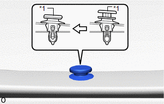
| (c) Attach the pin to install the clip as shown in the illustration. |
|
33. INSTALL BACK DOOR SIDE GARNISH RH
HINT:
Use the same procedure as for the LH side.
34. INSTALL BACK DOOR CENTER GARNISH
(a) Attach the 2 guides, 5 claws to install the back door center garnish.
35. INSTALL REAR WIPER MOTOR GROMMET
Click here
36. INSTALL REAR WIPER ARM AND BLADE ASSEMBLY
Click here
37. INSTALL REAR WIPER ARM HEAD CAP
Click here
38. INSPECT POWER BACK DOOR SYSTEM (w/ Power Back Door)
Click here
39. ADJUST REAR TELEVISION CAMERA ASSEMBLY
Click here
READ NEXT:
 Components
COMPONENTS ILLUSTRATION *A w/ Woofer *B w/o Woofer *1 BACK DOOR CENTER GARNISH *2 BACK DOOR LOCK COVER *3 BACK DOOR SIDE GARNISH LH *4 BACK DOOR SIDE GARNISH RH *5
Removal
REMOVAL PROCEDURE 1. REMOVE BACK DOOR CENTER GARNISH Click here 2. REMOVE BACK DOOR SIDE GARNISH LH Click here 3. REMOVE BACK DOOR SIDE GARNISH RH Click here 4. REMOVE BACK DOOR TRIM BASE Cli
SEE MORE:
Replacement
REPLACEMENT PROCEDURE 1. REPLACE INTAKE VALVE GUIDE BUSH (a) Heat the cylinder head sub-assembly to approximately 80 to 100°C (176 to 212°F). (b) Place the cylinder head sub-assembly on wooden blocks. (c) Using SST and a hammer, tap out the intake valve guide bush. SST: 09201-01055 SST: 09950-7
Inspection
INSPECTION PROCEDURE 1. INSPECT AIR CONDITIONING CONTROL ASSEMBLY (SEAT BELT WARNING LIGHT) (for Rear Side) (a) Check the seat belt warning light illumination. OK: Measurement Condition Specified Condition Battery positive (+) → Terminal 8 (IG+) Battery negative (-) → 1 (RRID) RH
