Lexus NX: Removal
REMOVAL
PROCEDURE
1. PRECAUTION
Click here .gif)
2. REMOVE FRONT BUMPER COVER
(a) for Sport Pacakge:
Click here
(b) except Sport Pacakge:
Click here
3. REMOVE NO. 3 ENGINE ROOM WIRE
(a) for Sport Pacakge:
Click here
(b) except Sport Pacakge:
Click here
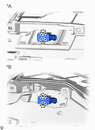
4. REMOVE FRONT CORNER ULTRASONIC SENSOR
| (a) Detach the 2 claws and remove the front corner ultrasonic sensor. HINT:
|
|
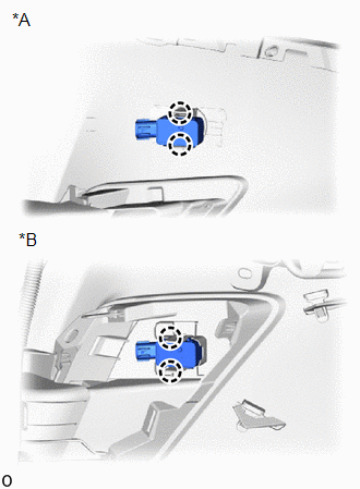
5. REMOVE FRONT CENTER ULTRASONIC SENSOR
| (a) Detach the 2 claws and remove the front center ultrasonic sensor. HINT:
|
|
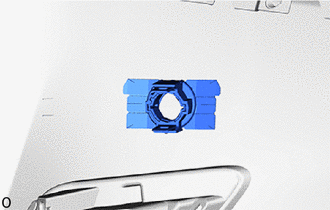
6. REMOVE FRONT CORNER ULTRASONIC SENSOR RETAINER (except Sport Package)
HINT:
- When removing the front corner ultrasonic sensor retainer, heat the front bumper assembly and front corner ultrasonic sensor retainer using a heat light.
- Use the same procedure for both front corner ultrasonic sensor retainers.
Standard:
| Item | Temperature |
|---|---|
| Front Bumper Assembly | 20 to 30°C (68 to 86°F) |
| Front Corner Ultrasonic Sensor Retainer |
NOTICE:
- Do not heat the front bumper assembly on front corner ultrasonic sensor retainer excessirely.
- Do not reuse the removed front corner ultrasonic sensor retainer.
| (a) Remove the front corner ultrasonic sensor retainer. |
|
7. REMOVE ULTRASONIC SENSOR CUSHION SET
HINT:
Perform the following procedure only when replacement of a ultrasonic sensor cushion set is necessary.
(a) Remove the ultrasonic sensor cushion set as shown in the illustration.
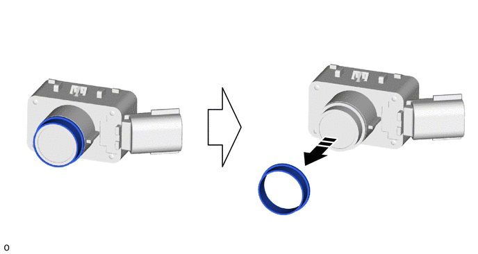
 | Remove in this Direction | - | - |
READ NEXT:
 Inspection
INSPECTION PROCEDURE 1. INSPECT FRONT CENTER ULTRASONIC SENSOR (a) Measure the resistance according to the value(s) in the table below. Standard Resistance: Tester Connection Condition Spec
Installation
INSTALLATION PROCEDURE 1. INSTALL ULTRASONIC SENSOR CUSHION SET HINT: Perform the following procedure only when replacement of a ultrasonic sensor cushion set is necessary. (a) Install the ultrasonic
SEE MORE:
Parts Location
PARTS LOCATION ILLUSTRATION *1 NO. 1 ENGINE ROOM RELAY BLOCK
EPB NO. 1 FUSE
EPB NO. 2 FUSE
HINT: EPB stands for Electric Parking Brake. *2 NO. 2 ENGINE ROOM RELAY BLOCK
ECU-B NO. 1 FUSE
ECU-B NO. 2 FUSE
*3 SKID CONTROL ECU (BRAKE BOOSTER WITH MASTER CYLINDER ASSEMBLY)
Route cannot be Calculated
PROCEDURE 1. SET DESTINATION (a) Set another destination and check if the system can calculate the route correctly. OK: Route can be correctly calculated. OK NORMAL OPERATION NG PROCEED TO NEXT SUSPECTED AREA SHOWN IN PROBLEM SYMPTOMS TABLE
